
Three-phase alternating current motor

a three-phase alternating current and motor technology, applied in the direction of dynamo-electric components, dynamo-electric machines, electrical apparatus, etc., can solve the problems of insufficient compatibility with the need for miniaturization and large outer shape of the stator itself, and achieve the effect of reducing costs and enhancing mountability

Active Publication Date: 2016-03-15
MITSUBISHI HEAVY IND THERMAL SYST
View PDF12 Cites 1 Cited by
  • Summary
  • Abstract
  • Description
  • Claims
  • Application Information

AI Technical Summary

Benefits of technology

This configuration enables miniaturization and cost reduction of the motor by securing space inside the insulating bobbins for connecting wires and neutral points, enhancing mountability and simplifying the winding structure while protecting the neutral point with a welded structure and protective cover.

Problems solved by technology

Therefore, the outer shape of the stator itself tends to be large, which is not sufficiently compatible with the need for miniaturization of the motor.

Method used


Image

  • Three-phase alternating current motor
  • Three-phase alternating current motor
  • Three-phase alternating current motor

Examples


first embodiment

[0035]Hereinafter, a first embodiment of the present invention will be described with reference to FIGS. 1 to 8.

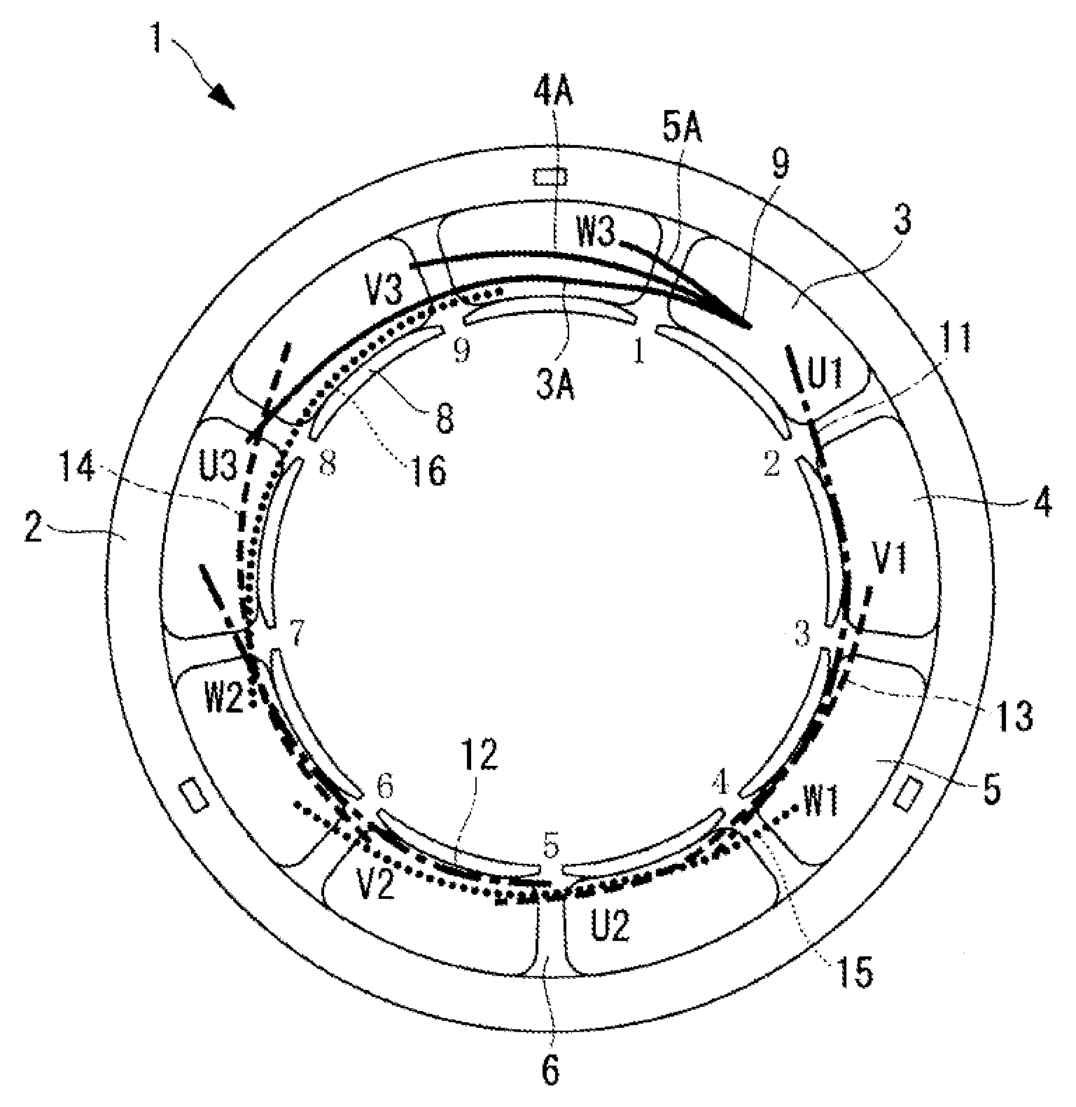
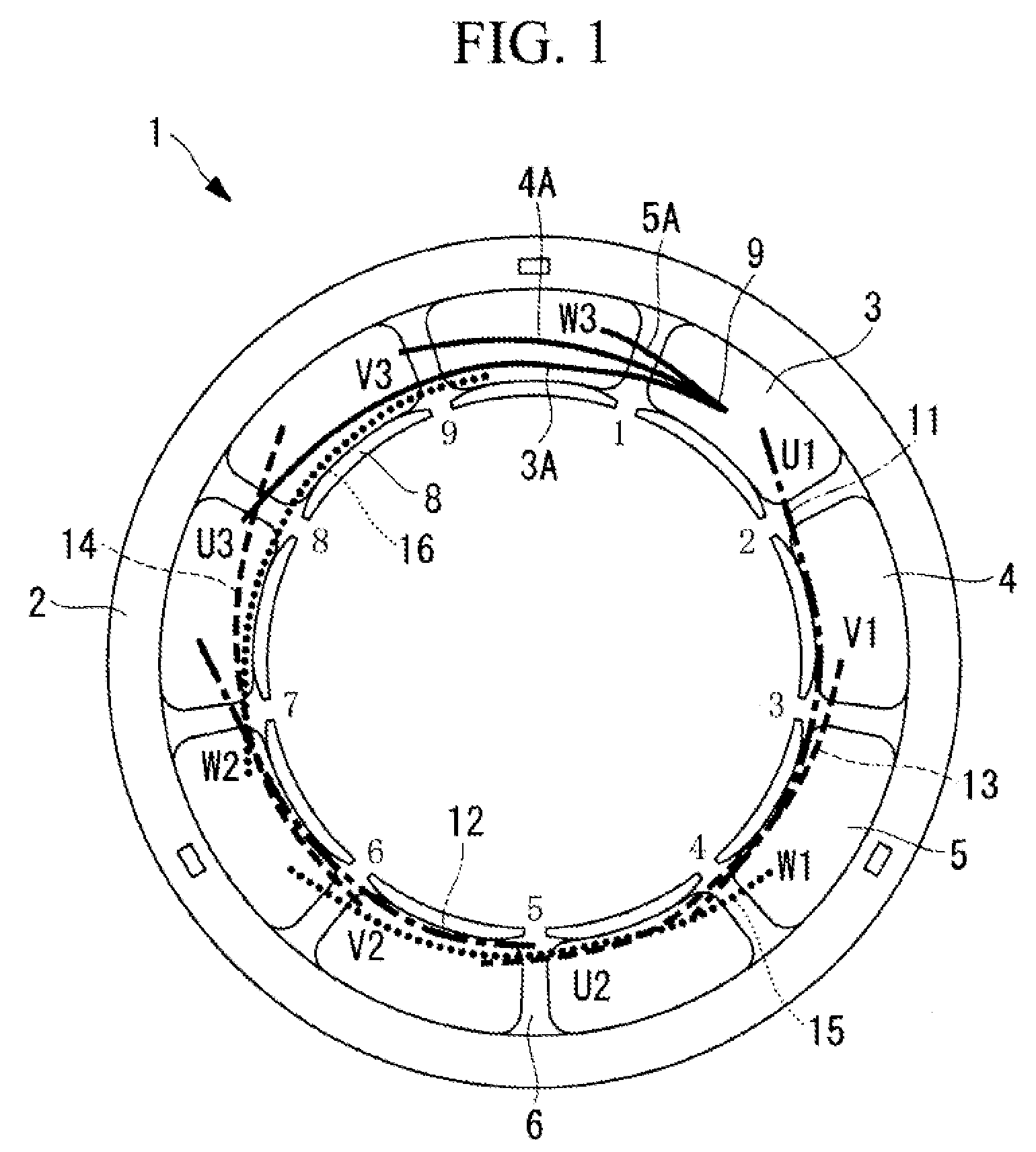
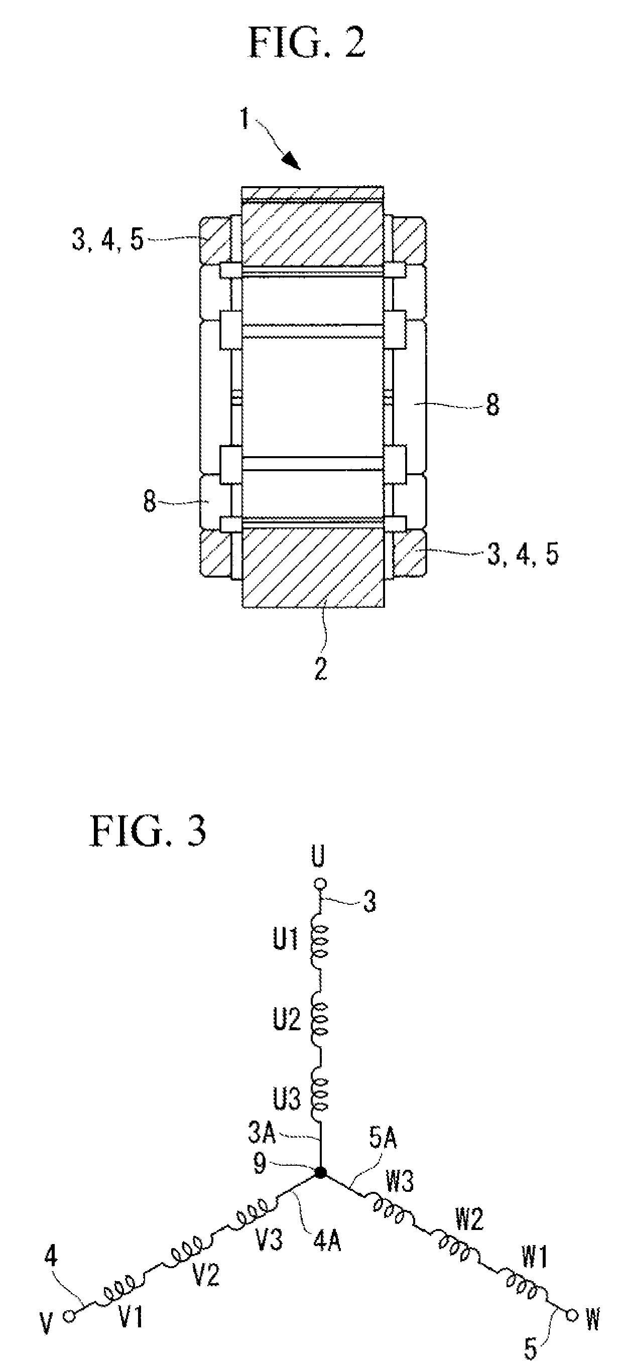
[0036]FIG. 1 shows a plan view of a stator of a three-phase AC motor according to the first embodiment of the present invention. FIG. 2 shows a view corresponding to a vertical section thereof. FIG. 3 shows a schematic diagram of a state of wire connecting of stator winding wires of respective phases thereof.

[0037]A stator 1 is configured by winding stator winding wires 3, 4 and 5 of respective phases U, V and W on a stator iron core 2 formed in a cylindrical shape.

[0038]The stator iron core 2 is configured by laminating a predetermined number of ring-shaped plate materials shaped by punching an electromagnetic steel plate or the like into predetermined shapes, and integrally bonding the plate materials by caulking, welding or the like. As shown in FIG. 4, on an inner circumferential surface side of the stator iron core 2, slots 6 to be winding spaces are provided at a plu...

second embodiment

[0055]Next, a second embodiment of the present invention will be described with reference to FIG. 9.

[0056]The present embodiment differs from the first embodiment described above in that a stopper 19 and a lid portion 20 are provided for the flange portions of the insulating bobbin 8. The other features are similar to the first embodiment, and therefore, the descriptions for the features will be omitted.

[0057]As shown in FIG. 9, the present embodiment adopts a configuration in which the stopper 19 that is protruded toward the outside diameter direction is provided at an end portion in the axial direction of the radial inside flange portion 8A of each of the insulating bobbins 8, or the openable and closable lid portion 20 for closing an end portion in the axial direction of the bobbin 8 is provided at an end portion in the axial direction of the radial outside flange portion 8B of each of the insulating bobbins 8, so that the connecting wires 11 to 16 of 3, 4 and 5 and the neutral p...


PUM


Abstract

When stator winding wires of respective phases are concentratedly wound on a plurality of tooth portions provided on a stator iron core via insulating bobbins the stator winding wires of the respective phases are wound in winding spaces in slot sides so that winding heights become gradually higher toward outside diameter sides from inside diameter sides of the insulating bobbins, and in spaces formed by the stator winding wires, at the radial insides of the insulating bobbins, at outsides in an axial direction relative to the stator winding wires, connecting wires of the stator winding wires of the respective phases and a neutral point at which distal ends thereof are star-connected are placed along the spaces.

Description

TECHNICAL FIELD[0001]The present invention relates to a three-phase AC (alternating current) motor suitable for being applied as a motor that drives an electric compressor of a vehicle air conditioner, or the like.BACKGROUND ART[0002]In a vehicle air conditioner that is mounted on an electric vehicle, a hybrid vehicle, or the like, an electric compressor with an inverter integrally installed in the compressor is used. In such electric compressors, a three phase AC motor to which three-phase alternating current power converted via an inverter is applied is used as the motor for driving the compressor. Such an inverter-integrated electric compressor is required to be miniaturized as much as possible for being mounted in the inside of an engine room, and accordingly the motor is also eagerly required to be miniaturized.[0003]As the above described three-phase AC motor, a concentrated wound (also called series wound) motor is used, and in the stator thereof, the connecting wires of stat...

Claims


Application Information

Patent Timeline
Patent Type & Authority Patents(United States)
IPC IPC(8): H02K23/40H02K3/28H02K3/52
CPCH02K3/28H02K3/522
Inventor HATTORI, MAKOTOISOBE, SHINICHISASAKI, MIKITO
Owner MITSUBISHI HEAVY IND THERMAL SYST
Learn More