Conveyor chain link, conveyor chain and conveyor system comprising conveyor chain

a technology of conveyor chain and chain link, which is applied in the direction of conveyors, transportation and packaging, etc., can solve the problems of not always being able to select a low friction material for the conveyor chain, and being unable to manufacture the complete chain link in metal, so as to achieve the effect of reducing the wear of the slide rail, reducing the friction material, and reducing the friction of the chain link

Inactive Publication Date: 2016-03-22
FLEXLINK
View PDF18 Cites 5 Cited by
  • Summary
  • Abstract
  • Description
  • Claims
  • Application Information

AI Technical Summary

Benefits of technology

[0022]The upper body is also provided with sideway bearing surfaces adapted to carry forces perpendicular to the centre line of the chain link. The sideway bearing surface may be provided with an acute angle in relation to the centre line of the chain link. In this way, the sideway bearing surface will be able to take up sideway forces.
[0024]The advantage of manufacturing the chain link in two parts is that different materials can be used for the upper body and the lower body. The lower body can be manufactured in a low friction material. The upper body can be manufactured in a material adapted for the use of the conveyor chain. One such use would be a conveyor chain adapted for ESD use. Since the material must be a conductive or static dissipative material, the material must contain conducting particles embedded in the material, such as graphite powder, which will weaken the material. Thus, the upper conductive part of the conveyor chain can be made from one material and the lower part can be made in another material, which has a higher wear resistance.
[0025]Another advantage is that the upper body can be made from a metallic material. To manufacture a complete conveyor chain link from a metallic material is both costly and difficult and is further not desirable since the wear on the slide rails of the conveyor beams will be higher for such a conveyor chain and because such a chain link will be relatively heavy. With the upper part of the chain link made from a metallic material, the wear of the slide rails is minimized. Since the upper part does not have any resilient catches, the upper part can be made of a non-resilient material, such as stainless steel. A further advantage of not having resilient catches to hold the upper body and lower body together is that there is no risk that a resilient catch will come loose during use of the conveyor chain or when the conveyor chain is caught up in something and jams.

Problems solved by technology

One problem with a sliding contact between the conveyor chain and the conveyor beams is that friction is created.
It is however not always possible to select a low friction material for the conveyor chain.
It is however complicated to manufacture the complete chain link in metal.
With such a solution, there is a risk that the catches disengage unintentionally, e.g. when the conveyor system has a malfunction or when an excessive force is applied to the conveyor chain link.

Method used


Image

  • Conveyor chain link, conveyor chain and conveyor system comprising conveyor chain
  • Conveyor chain link, conveyor chain and conveyor system comprising conveyor chain
  • Conveyor chain link, conveyor chain and conveyor system comprising conveyor chain

Examples


Embodiment Construction

[0033]The embodiments of the invention with further developments described in the following are to be regarded only as examples and are in no way to limit the scope of the protection provided by the patent claims.

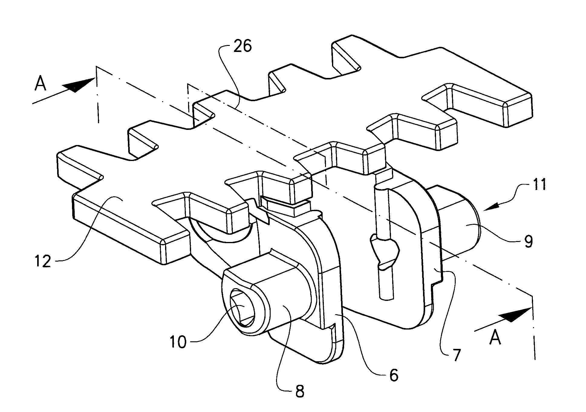
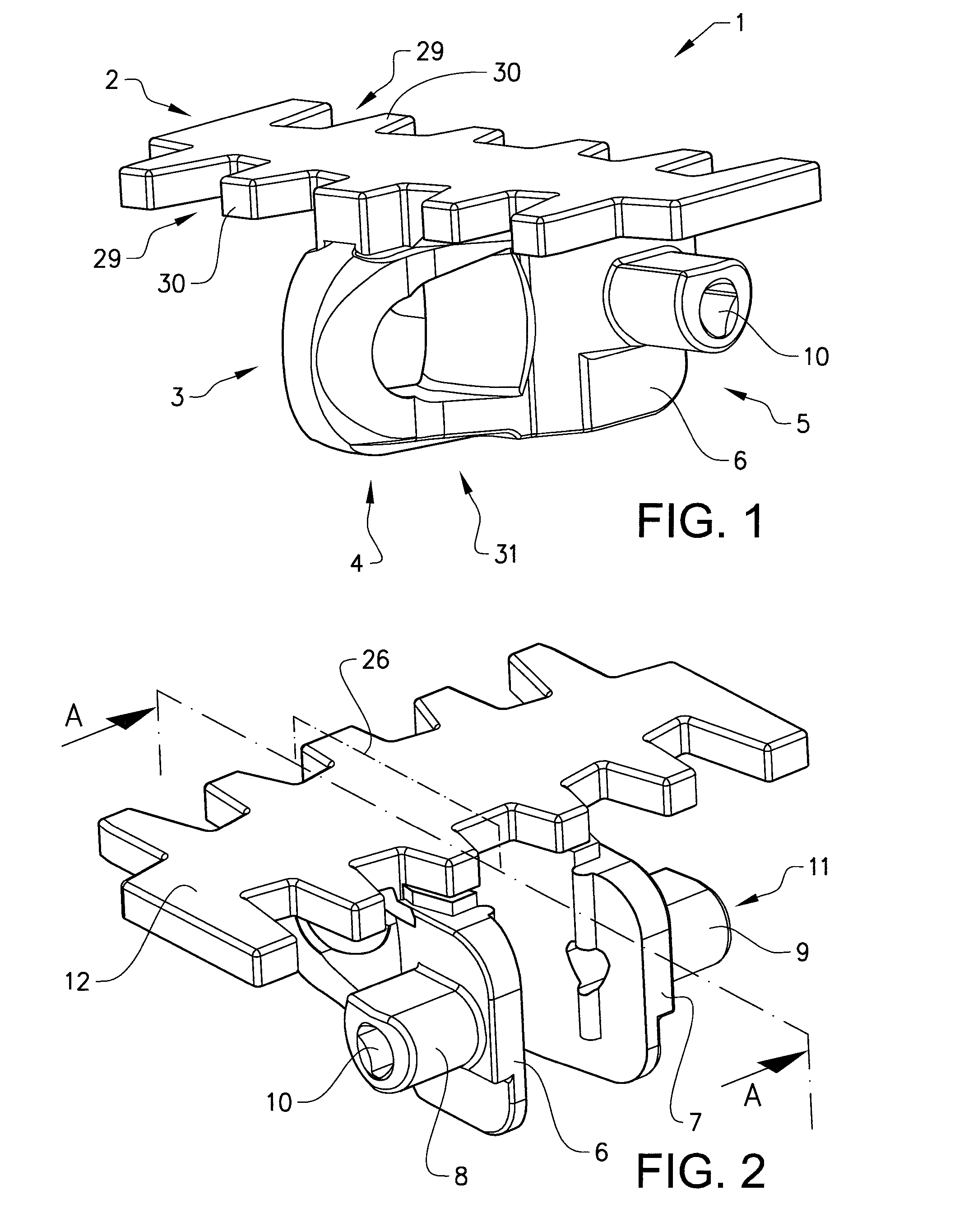
[0034]In FIGS. 1 and 2, a chain link 1 which can form a part of a conveyor chain is shown. The chain link has an upper body 2 with an upper carrying surface 12 adapted to carry objects that are to be conveyed. The upper carrying surface is preferably shaped like a substantially flat surface having a plurality of notches 29 and teeth 30 arranged adjacent to the front end 4 and the rear end 5. The notches and the teeth are arranged to mesh with the corresponding notches and teeth of an adjacent chain link. Such upper body shapes are well-known in the art. Other upper body shapes are also conceivable.

[0035]The chain link is further provided with a lower body 3 which has a front end 4 and a rear end 5. The front end 4 has a substantially spherical bearing seat 31 which is arran...


PUM


Abstract

A conveyor chain link, comprising an upper body having a carrying surface, and a lower body having a front end and a rear end, where the upper body and the lower body are separate parts, where the upper body is provided with a longitudinal slot adapted to cooperate with a protruding tongue on the front end of the lower body, with at least one forward bearing surface arranged perpendicular to the center line of the chain link and adapted to bear on at least one first bearing surface of the lower body, with two sideway bearing surfaces adapted to bear on two second bearing surfaces of the lower body, and at least one locking means adapted to lock the upper body to the lower body fixedly and irremovably. The advantage of the chain link is that a chain link with different properties for the lower body and the upper body is provided for, where the upper and lower bodies are fixedly locked to each other.

Description

RELATED APPLICATIONS[0001]This application is a U.S. National Stage application filed under 35 U.S.C. §371 from International Application Serial No. PCT / SE2013 / 050308, filed Mar. 20, 2013 and published as WO 2013 / 141807 A1 on Sep. 26, 2013, which claims the priority benefit of Sweden Patent Application No.: 1250273-8, filed Mar. 20, 2012, the contents of which applications and publication are incorporated herein by reference in their entirety.TECHNICAL FIELD[0002]The present invention relates to a conveyor chain comprising two different materials and a conveyor chain comprising a plurality of such conveyor chain links. The conveyor chain link is adapted to be used in a conveyor system comprising an endless chain.BACKGROUND ART[0003]Conveying devices, such as those which are used for moving objects between different stations in a factory, usually comprise a conveying track in the form of a belt or a chain. The conveying tracks can be recessed in a trench with vertical side surfaces. ...

Claims


Application Information

Patent Timeline
Patent Type & Authority Patents(United States)
IPC IPC(8): B65G17/06B65G17/08B65G17/44B65G17/40
CPCB65G17/40B65G17/08B65G17/086B65G17/44B65G17/06B65G17/066
Inventor ABBESTAM, GORAN
Owner FLEXLINK
Why Eureka
Try Eureka