Equipment enclosure and method of installation to facilitate servicing of the equipment

a technology for equipment and enclosures, applied in lighting and heating apparatus, ventilation systems, heating types, etc., can solve problems such as roof membrane failure and moisture leakage, and achieve the effects of reducing the number of roof penetrations

Inactive Publication Date: 2016-03-22
DEMSTER STANLEY J
View PDF57 Cites 10 Cited by
  • Summary
  • Abstract
  • Description
  • Claims
  • Application Information

AI Technical Summary

Benefits of technology

[0012]The invention described herein allows mechanical equipment for building systems or processes, such as HVAC equipment, to be installed so that the equipment is recessed into the roof when in service but which may be raised above the roof for maintenance to avoid the drawbacks of the traditional “above curb” configuration. The invention comprises an equipment enclosure which is designed to be recessed into the roof such that an upper end of the enclosure above or at the top of the curb. The invention allows the mechanical equipment to be recessed such that there is minimal, if any, projection of the mechanical equipment above the top of the roof curb or the roof. The invention also includes a means to allow physical access to the equipment via a covered access opening on the equipment enclosure which may also include a mechanism that raises the equipment to a more accessible location. By recessing mechanical equipment such as HVAC equipment into the roof opening framed by the curb, the invention minimizes the equipment's exposure to damaging weather, and also improves the aesthetics of the equipment installation. In some installations, the rooftop equipment may be virtually invisible when viewed from ground level.
[0015]The equipment enclosure system may provide conventional ductwork connections to the cabinet below the roof plane, similar to traditional connections. One difference between the improved system and traditional rooftop equipment cabinets is that the improved system allows the enclosure or cabinet to recess within the curb and the interstitial space below the roof skin rather than positioning the cabinet on top of the roof curb. Traditionally, the interstitial space below the curb and roof is used for connecting ductwork serving the unit or for adding an occasional field installed item like a damper, smoke detector, heat wheel or similar auxiliary device. The present system can significantly reduce the number of roof penetrations required with a traditional roof curb mounting. This is beneficial because roof penetrations are often the cause of roof membrane failure and moisture leakage.
[0016]The invention has several objectives. The primary objective is to conceal most if not all of the mechanical equipment while protecting the equipment from the forces of nature like strong winds and hail. A secondary objective is a reduction in the number of roof penetrations caused by screening systems and equipment connections. Another secondary objective is to reduce energy losses associated with the equipment cabinet by reducing the amount of cabinet area exposed to the outdoor elements. Lastly, the invention improves access to the equipment components while eliminating troublesome access doors and hatches.

Problems solved by technology

This is beneficial because roof penetrations are often the cause of roof membrane failure and moisture leakage.

Method used


Image

  • Equipment enclosure and method of installation to facilitate servicing of the equipment
  • Equipment enclosure and method of installation to facilitate servicing of the equipment
  • Equipment enclosure and method of installation to facilitate servicing of the equipment

Examples


Embodiment Construction

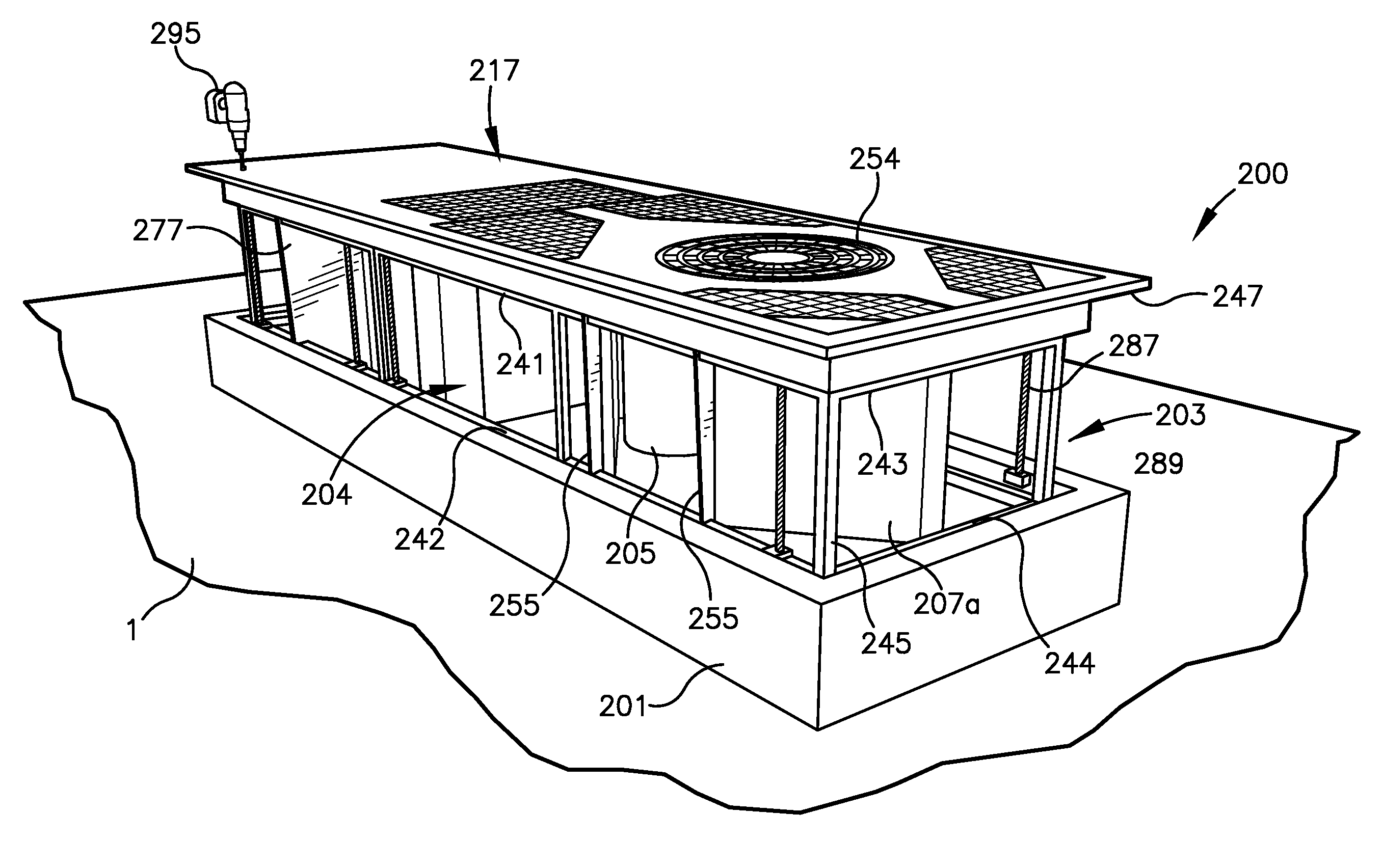
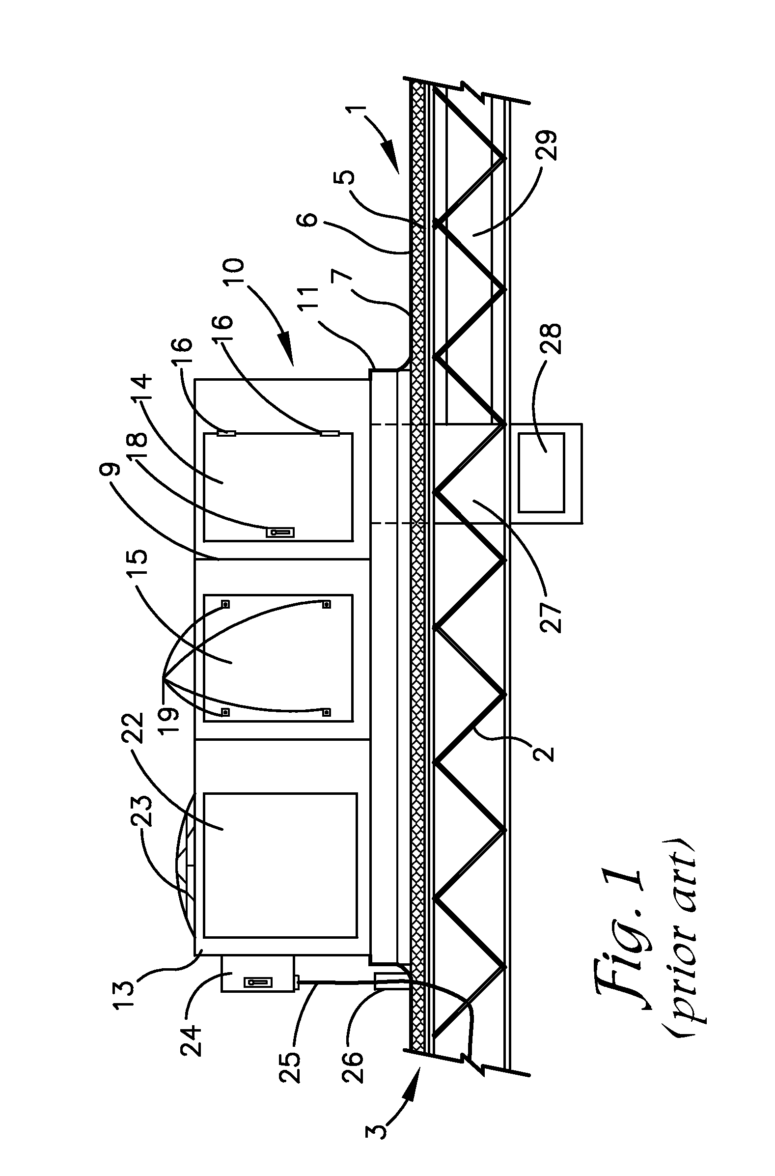
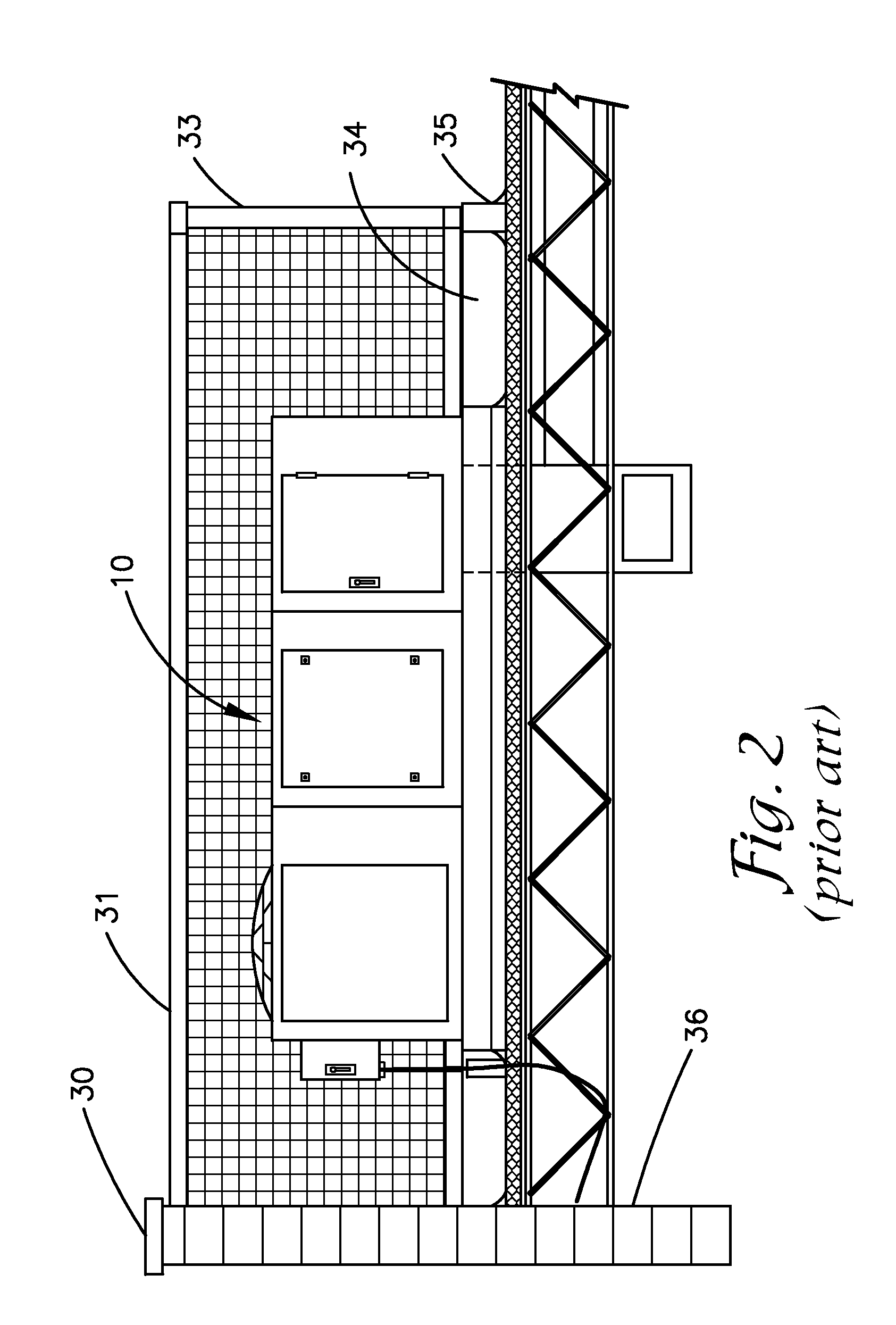
[0035]As required, detailed embodiments of the present invention are disclosed herein; however, it is to be understood that the disclosed embodiments are merely exemplary of the invention, which may be embodied in various forms. Therefore, specific structural and functional details disclosed herein are not to be interpreted as limiting, but merely as a basis for the claims and as a representative basis for teaching one skilled in the art to variously employ the present invention in virtually any appropriately detailed structure. The drawings constitute a part of this specification and include exemplary embodiments of the present invention and illustrate various objects and features thereof.

[0036]Certain terminology will be used in the following description for convenience in reference only and will not be limiting. For example, the words “upwardly,”“downwardly,”“rightwardly,” and “leftwardly” will refer to directions in the drawings to which reference is made. The words “inwardly” a...


PUM


Abstract

An equipment enclosure system includes an equipment enclosure mounted through a hole in a roof and a chassis supporting the mechanical equipment and which is moveable between a lowered position within the enclosure and a raised position relative to the enclosure to provide access to said equipment. A cover mounted on chassis advances into covering relationship over the enclosure when the chassis is retracted.

Description

FIELD OF THE INVENTION[0001]The present invention relates to enclosures for equipment which facilitate access to the equipment for maintenance. More specifically, the present invention relates to mounting equipment such as rooftop heating, cooling or ventilation equipment through the roof and into the interstitial space below the roof.BACKGROUND OF THE INVENTION[0002]A common technique used to install heating, ventilation and air conditioning (HVAC) equipment, or other mechanical equipment for supporting building systems or processes, on a roof is to mount the equipment on a curb that rests on the surface of the roof. Generally, the section of roof that is framed by the curb is removed to allow ducts, pipes or electrical conduit to attach to the equipment. Using a curb is beneficial to installing the equipment directly on the roof surface for reasons such as avoiding damage to roofing materials, not blocking roof drainage paths, ensuring the equipment is above standing water or snow...

Claims


Application Information

Patent Timeline
Patent Type & Authority Patents(United States)
IPC IPC(8): F24F7/02F24F1/02E04B7/16
CPCF24F1/022E04B7/16E04B7/166F24F2221/16
Inventor DEMSTER, STANLEY, J.
Owner DEMSTER STANLEY J
Why Eureka
Try Eureka