
Ambient sound velocity obtaining method and apparatus

a technology of ambient sound and obtaining method, applied in the direction of instruments, ultrasonic/sonic/infrasonic image/data processing, ultrasonic/sonic/infrasonic diagnostics, etc., can solve the problems of image quality degradation, inability to obtain appropriate contrast, and inability to obtain ambient sound velocity of subj

Active Publication Date: 2016-03-22
FUJIFILM CORP
View PDF10 Cites 0 Cited by
  • Summary
  • Abstract
  • Description
  • Claims
  • Application Information

AI Technical Summary

Benefits of technology

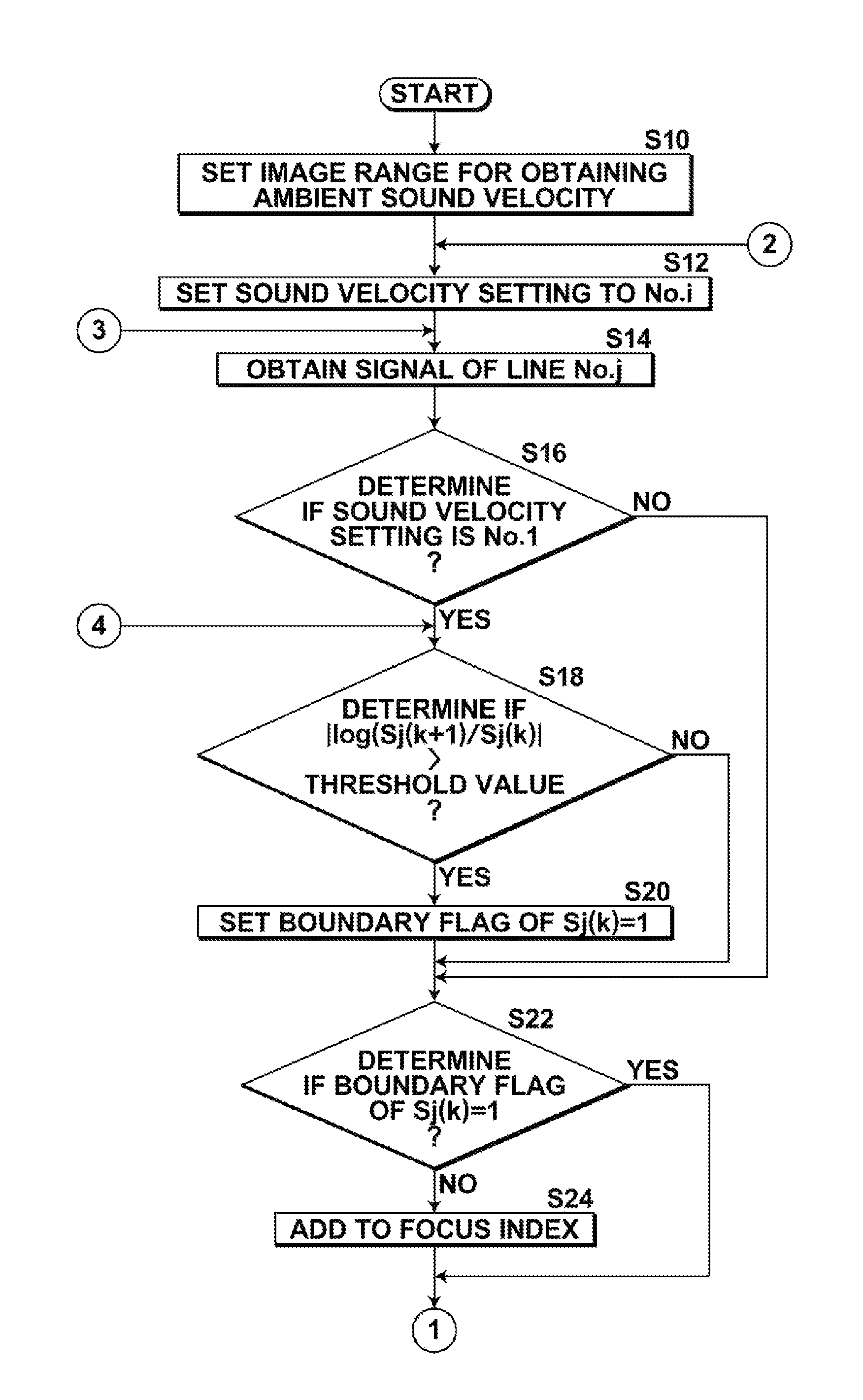
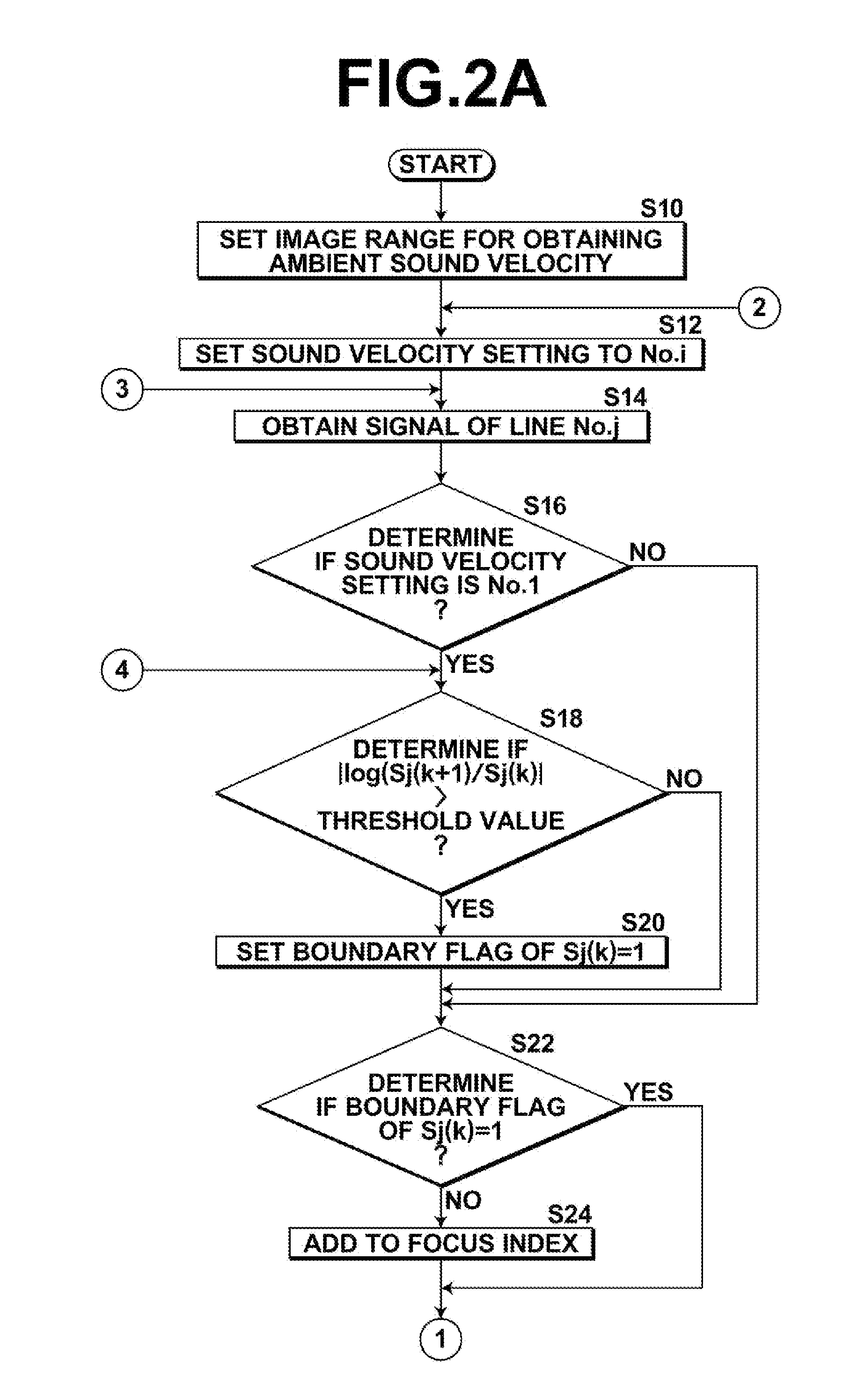
[0026]According to the ambient sound velocity obtaining method and apparatus of the present invention, in an ambient sound velocity obtaining method in which receive focusing is performed on a receive signal obtained by the ultrasonic probe using receive delay times based on a plurality of sound velocity settings to obtain in-phase sum signals with respect to each sound velocity setting, and an ambient sound velocity of the subject is obtained based on the obtained in-phase sum signals with respect to each sound velocity setting, the in-phase sum signals with respect to each sound velocity setting are separated into an in-phase sum signal corresponding to a boundary portion in the subject and an in-phase sum signal corresponding to a portion other than the boundary portion, an index based on at least either one of the in-phase sum signal corresponding to the boundary portion and the in-phase sum signal corresponding to the portion other than the boundary portion is obtained, and the ambient sound velocity is obtained based on the obtained index. This allows a high accurate ambient sound velocity to be obtained without being influenced by a reflection at a boundary portion described above.
[0028]In the ambient sound velocity obtaining method and apparatus of the present invention, if an arrangement is adopted in which the ultrasonic wave focused on a plurality of transmit focus positions is transmitted with respect to each transmit focus position, an index of the boundary portion and an index of the portion other than the boundary portion are obtained with respect to each transmit focus position, a difference between a provisional ambient sound velocity obtained base on the index of the boundary portion and a provisional ambient sound velocity obtained based on the index of the portion other than the boundary portion is obtained with respect to each transmit focus position, and a provisional ambient sound velocity obtained based on the index of the boundary portion or the index of the portion other than the boundary portion corresponding to a transmit focus position where the difference obtained becomes minimal is obtained as the ambient sound velocity of the subject, the ambient sound velocity when the transmit focus position is set to the boundary section may be obtained easily and a high accurate ambient sound velocity may be obtained.

Problems solved by technology

But, the ambient sound velocity of a subject is not constant and differs from tissue to tissue, and if the assumed sound velocity differs from the ambient sound velocity, a problem of image quality degradation may arise.
Further, if the boundary surface is not parallel to the probe surface or curved, more complicated reflection behaviors are seen, and the ambient sound velocity at the boundary portion differs from that of a portion other than the boundary portion after all.
Therefore, receive focusing performed by setting sound velocity settings without making a distinction between the boundary portion and a portion other than the boundary portion, as in the method described in Japanese Unexamined Patent Publication No. 2009-089940, may result in that appropriate contrasts may not be obtained due to noise caused by the contrast at the boundary portion, so that an ambient sound velocity of a subject may not be obtained.

Method used


Image

  • Ambient sound velocity obtaining method and apparatus
  • Ambient sound velocity obtaining method and apparatus
  • Ambient sound velocity obtaining method and apparatus

Examples


first embodiment

[0092]As sound velocity setting No.j, No.1 to No.251 of 1400 m / s to 1650 m / s are preset in the scanning control section 16 as in the

[0093]The line No.k represents in-phase sum signals of one column extending in a depth direction of the subject and is a line set within the range for obtaining the ambient sound velocity. In the present embodiment, 16 columns of lines No.1 to No.16 are used, as illustrated in FIG. 3.

[0094]Then, if the sound velocity setting used for the receive focusing is No.1, that is the sound velocity setting set first (S48), a determination is made as to whether or not each in-phase sum signal S1(l) is that belonging to a boundary portion of the subject and a flag is set to the coordinate value of each in-phase sum signal of the line No.1, as in the first embodiment (S50). Note that l represents a depth of the subject within the range for obtaining the ambient sound velocity of the subject.

[0095]Then, an in-phase sum signal at a depth l to which the boundary flag=...

second embodiment

[0115]So far, the ambient sound velocity obtaining method of the second embodiment has been described.

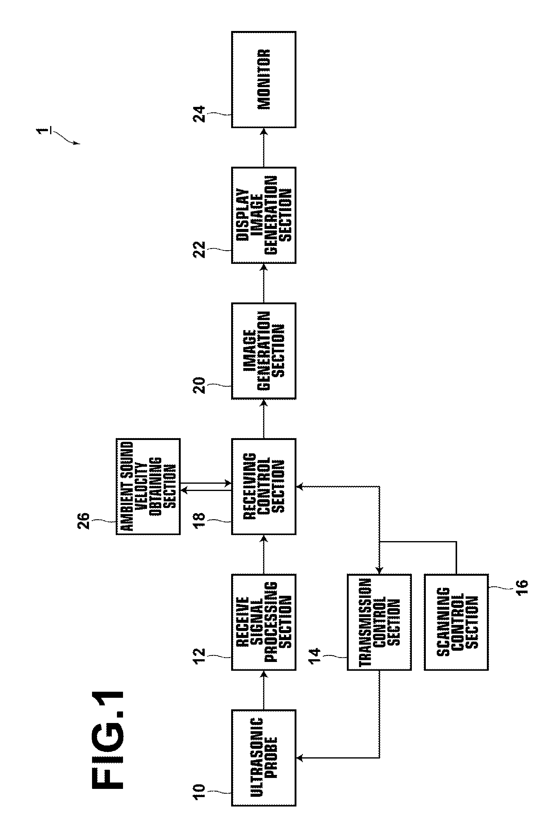
[0116]Then, the ambient sound velocity of the subject obtained by the ambient sound velocity obtaining method of the first or second embodiment may be displayed on the monitor 24 as numerical information upon receipt of an operator instruction. Alternatively, an arrangement may be adopted in which transmit delay times based on the obtained ambient sound velocity and receive delay times are calculated, then transmit focusing is performed base on the calculated transmit delay times and receive focusing is performed using the receive delay times to generate an ultrasonic image signal, and an ultrasonic image based on the ultrasonic image signal is displayed on the monitor 24.

[0117]In the description of the second embodiment, the provisional ambient sound velocity of the portion other than the boundary portion at the transmit focus position where the difference of provisional ambient so...


PUM

PropertyMeasurementUnit
depthaaaaaaaaaa
depthaaaaaaaaaa
sizeaaaaaaaaaa

Abstract

To obtain ambient sound velocity of a subject with high accuracy in a ultrasonic diagnosis apparatus. In an ambient sound velocity obtaining method that transmits ultrasonic waves from an ultrasonic probe, receives reflected waves reflected by a subject to obtain received signals, performs a receive focusing process on the received signals using receive delay times based on a plurality of sound velocity settings to obtain in-phase sum signals with respect to each sound velocity setting, and obtains an ambient sound velocity of the subject based on the in-phase sum signals with respect to each sound velocity setting, the in-phase sum signals with respect to each sound velocity setting is separated into an in-phase sum signal corresponding to a boundary portion in the subject and an in-phase sum signal corresponding to portions other than the boundary portion, an index is obtained based on at least either one of the in-phase sum signals, and the ambient sound velocity is obtained based on the index.

Description

CROSS REFERENCE TO RELATED APPLICATIONS[0001]This application is a National Stage of International Application No. PCT / JP2011 / 001949 filed Mar. 31, 2011, claiming priority based on Japan Patent Application No. 2010-080596, filed Mar. 31, 2010, the contents of all of which are incorporated herein by reference in their entirety.TECHNICAL FIELD[0002]The present invention relates to a method and apparatus for obtaining an ambient sound velocity of a subject used in an ultrasonic diagnostic apparatus.BACKGROUND ART[0003]Ultrasonic diagnostic apparatuses for obtaining a tomographic image of a subject using ultrasonic waves for medical diagnosis have been proposed. In such an ultrasonic diagnostic apparatus, when transmitting ultrasonic waves from an ultrasonic probe, so-called transmit focusing in which a transmit delay time is set to each ultrasonic wave transmitted from each element of the ultrasonic probe is performed and when obtaining receive signals, so-called receive focusing in wh...

Claims


Application Information

Patent Timeline
Patent Type & Authority Patents(United States)
IPC IPC(8): G01N29/07A61B8/08G01S7/52
CPCG01N29/07A61B8/0858G01S7/52049
Inventor KATSUYAMA, KIMITO
Owner FUJIFILM CORP
Learn More