
Solid electrolytic capacitor

a solid electrolytic capacitor and capacitor technology, applied in the direction of electrolytic capacitors, capacitor details, capacitor housing/encapsulation, etc., can solve the problems of easy deterioration of the above-described problems, and achieve the effect of reducing the deterioration of the property of the solid electrolytic capacitor due to metal ion migration

Active Publication Date: 2016-03-22
TOKIN CORP +1
View PDF10 Cites 21 Cited by
  • Summary
  • Abstract
  • Description
  • Claims
  • Application Information

AI Technical Summary

Benefits of technology

This solution effectively suppresses metal ion generation and migration, reducing property deterioration and enhancing the humidity resistance of the solid electrolytic capacitor.

Problems solved by technology

In particular, if metal ions elute from a section of the anode terminal close to the capacitor element, the above-described problems will happen easily because an assumed path length of migration of metal ions is short.

Method used


Image

  • Solid electrolytic capacitor
  • Solid electrolytic capacitor
  • Solid electrolytic capacitor

Examples


Embodiment Construction

[0019]The present invention is related to an improved capacitor. More specifically, the present invention is related to an improved capacitor with a portion of the anode lead encased to prohibit migration of metal particles.

[0020]The invention will be described with reference to the figures which are an integral, but non-limiting part of the specification. Throughout the various figures similar elements will be numbered accordingly.

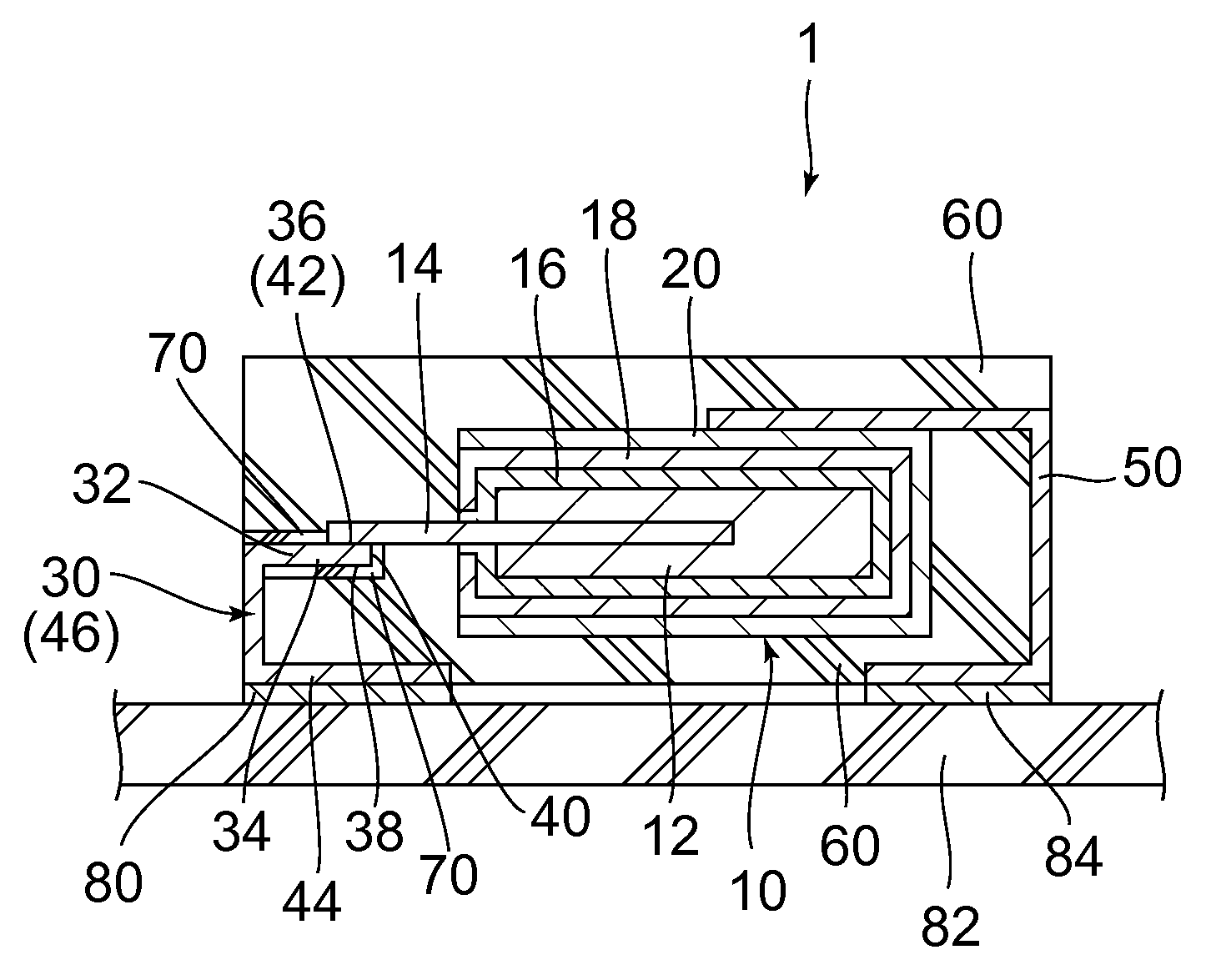
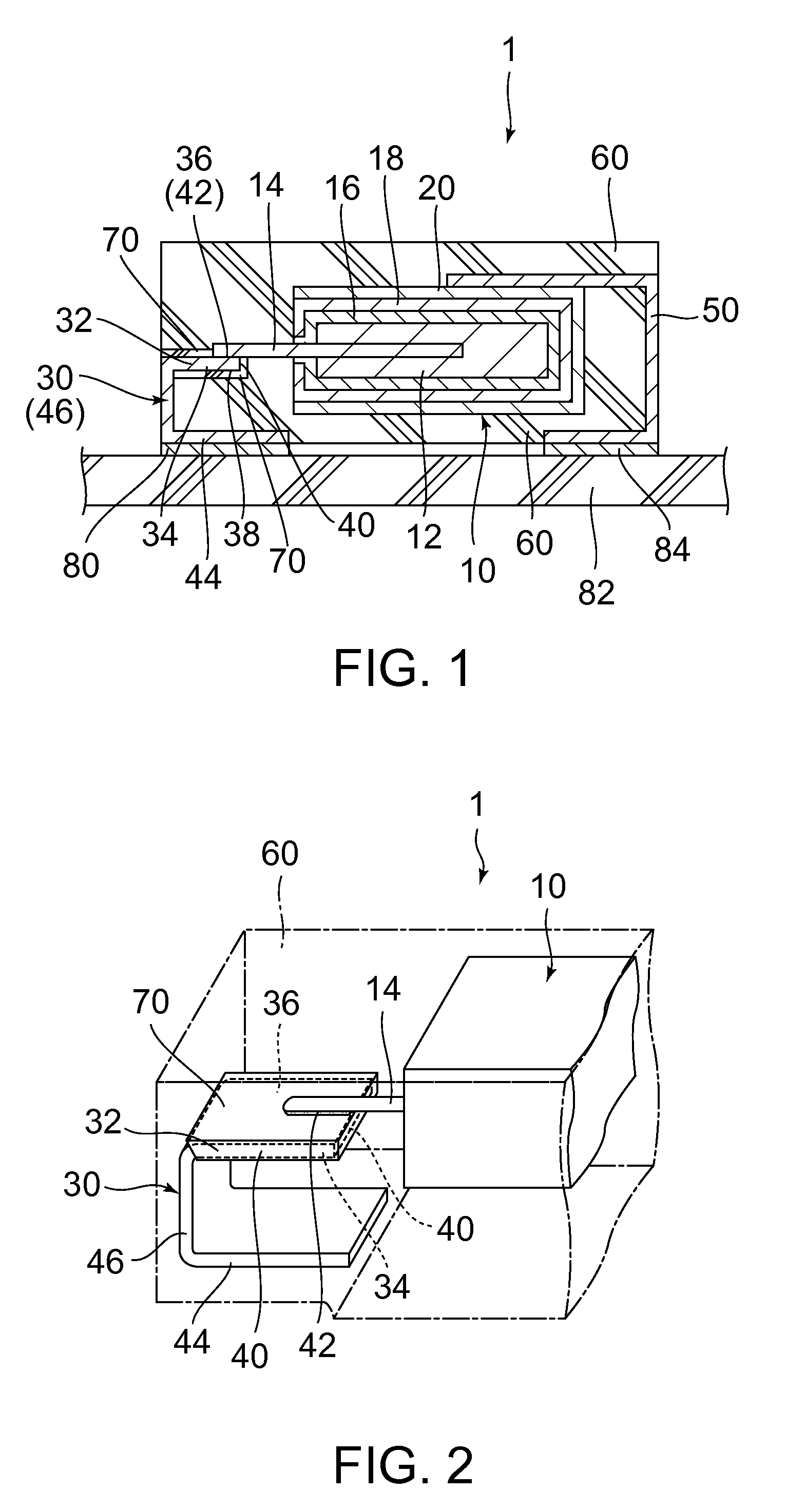
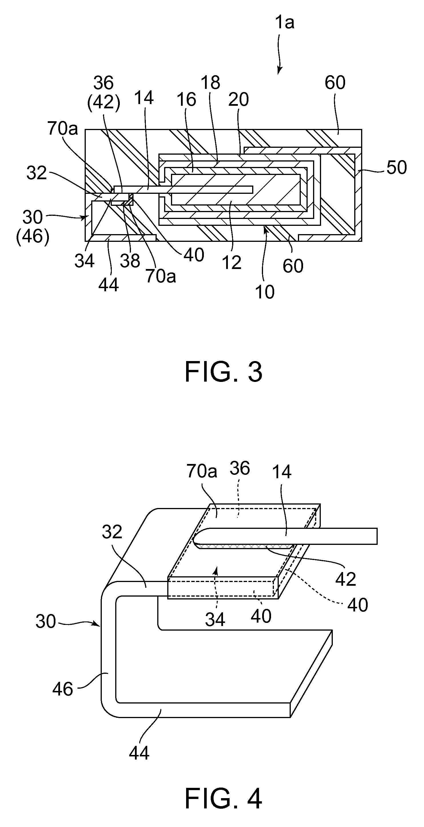
[0021]With reference to FIGS. 1 and 2, a solid electrolytic capacitor 1 according to an embodiment of the present invention comprises a capacitor element 10, an anode terminal 30, a cathode terminal 50, an outer insulation member 60 made of a first resin and a mask layer 70 made of a second resin, wherein the mask layer 70 partially covers the anode terminal 30. As shown in FIG. 1, the capacitor element 10 comprises an anode body 12 with a dielectric 16 thereon, an anode lead wire 14, a solid electrolyte layer 18, and a conductive layer 20 preferably comp...


PUM

PropertyMeasurementUnit
contact angleaaaaaaaaaa

Abstract

An outer insulation member made of a first resin packs a part of an anode terminal. The packed part of the anode terminal has a predetermined section. All surfaces of the predetermined section consist of a front surface, a back surface and edges connecting between the front surface and the back surface. The front surface includes a connection area. An anode lead wire is connected to the connection area while being not connected to the anode terminal other than the connection area. The all surfaces of the predetermined section are completely covered with a mask layer made of a second resin except for the connection area. The second resin is different from the first resin in at least one of composition thereof, content of an inclusion, size of an inclusion and shape of an inclusion.

Description

BACKGROUND OF THE INVENTION[0001]This invention relates to a solid electrolytic capacitor that has high humidity resistance.[0002]For example, a solid electrolytic capacitor is disclosed in JP2000-208367A, which is incorporated herein by reference. The disclosed solid electrolytic capacitor includes an anode body coated with a dielectric film, a solid electrolyte layer formed on the dielectric film, a cathode layer formed on the solid electrolyte layer, a cathode lead, an anode lead wire attached to or partially embedded in the anode body, an anode terminal connected to the anode lead wire, and an outer insulation member encasing all but a portion of the anode and cathode leads. The anode lead wire and the anode terminal may be connected to each other before the formation of the solid electrolyte layer. The connection portion between the anode lead wire and the anode terminal is covered with and fixed by resin, which is formed in a process different from the formation process of the...

Claims


Application Information

Patent Timeline
Patent Type & Authority Patents(United States)
IPC IPC(8): H01G9/12H01G9/10H01G9/15H01G9/012
CPCH01G9/012H01G9/10H01G9/15Y10T29/417
Inventor LIU, YANMINGYOSHIDA, YUJIUEDA, HAYATOTAKADA, DAISUKEIWAI, SATOSHIMIZUKOSHI, TAKASHI
Owner TOKIN CORP
Learn More