Centrifugal fan

a centrifugal fan and fan body technology, applied in the field of centrifugal fans, can solve the problems of limited inner space and extremely thin portability of portable computers, tablets or ultrabooks, and achieve the effects of reducing the dimensions of centrifugal fans disposed therein, increasing the force flow rate, and improving the heat dissipation

Active Publication Date: 2016-03-22
DELTA ELECTRONICS INC
View PDF4 Cites 4 Cited by
  • Summary
  • Abstract
  • Description
  • Claims
  • Application Information

AI Technical Summary

Benefits of technology

[0008]Utilizing the centrifugal fan of the embodiment of the invention, even though the inlet of the centrifugal fan is adjacent to other electronic elements, due to the step difference between the first peripheral structure and the second peripheral structure, the major flow is impelled into the inlet. The inlet diameter is greater than or equal to the impeller diameter, so the impelled flow rate is increased, and heat dissipation effect is improved. At least a portion of the first peripheral structure is located in the high pressure area to prevent flow leakage. Since tablet computers and the ultrabooks are extremely thin, the dimensions of the centrifugal fan disposed therein need to be decreased, and the height of the blades need to be decreased. However, the working area of the blades would need to be reduced. In the embodiment of the invention, the blades are extended to the outer surface of the peripheral structure around the inlet, thus, the height of the blades is increased, and the working area and heat dissipation effect thereof are improved.

Problems solved by technology

Portable computers (for example, tablet computers or ultrabooks) are extremely thin, and the inner space therein is limited.
The heat dissipation effect of the centrifugal fan has therefore deteriorated.
Particularly, with limited inner space, the input flow rate of the centrifugal fan has decreased, and the heat dissipation effect has worsened.

Method used


Image

  • Centrifugal fan
  • Centrifugal fan
  • Centrifugal fan

Examples


Embodiment Construction

[0016]The following description is of the best-contemplated mode of carrying out the invention. This description is made for the purpose of illustrating the general principles of the invention and should not be taken in a limiting sense. The scope of the invention is best determined by reference to the appended claims.

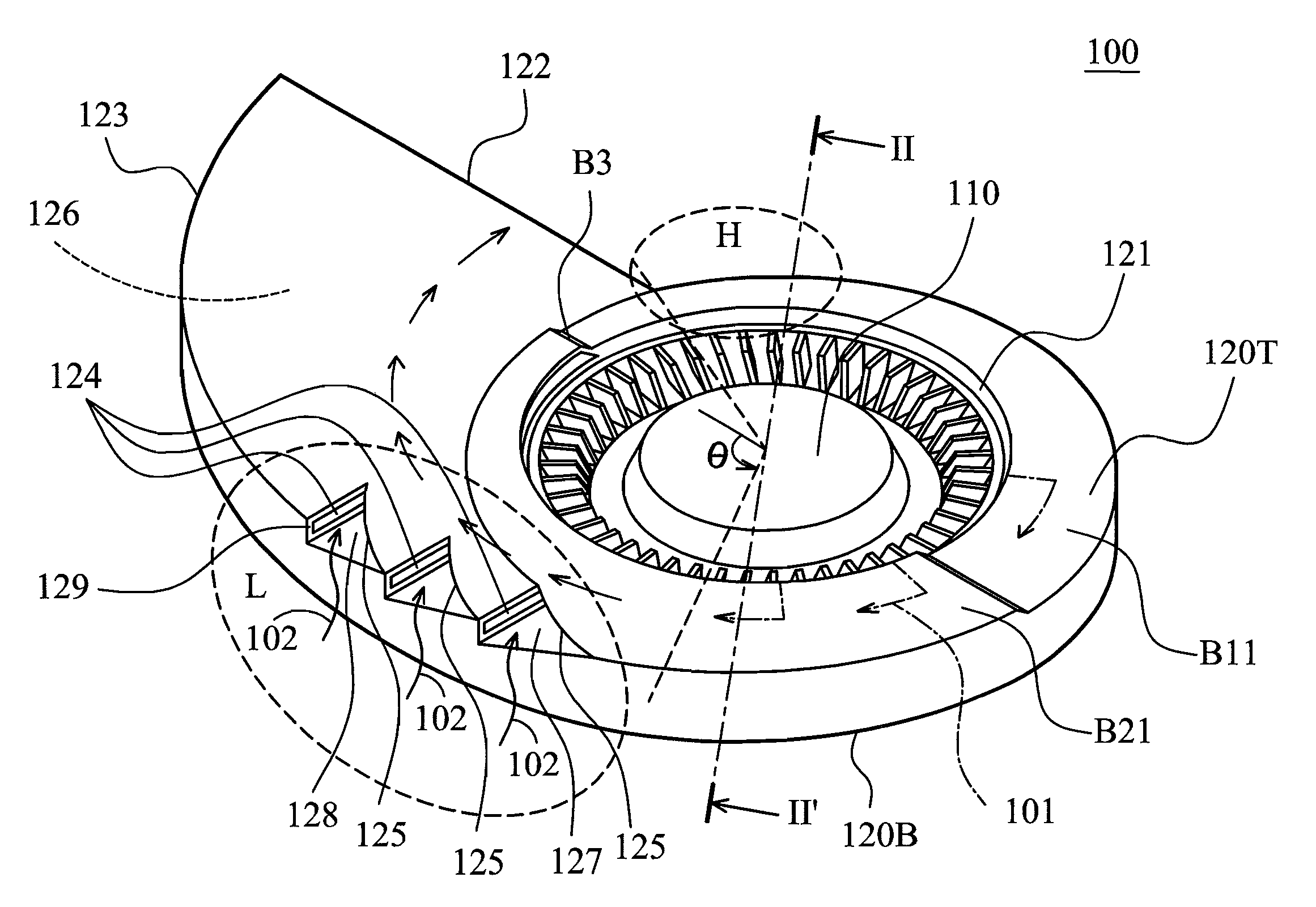
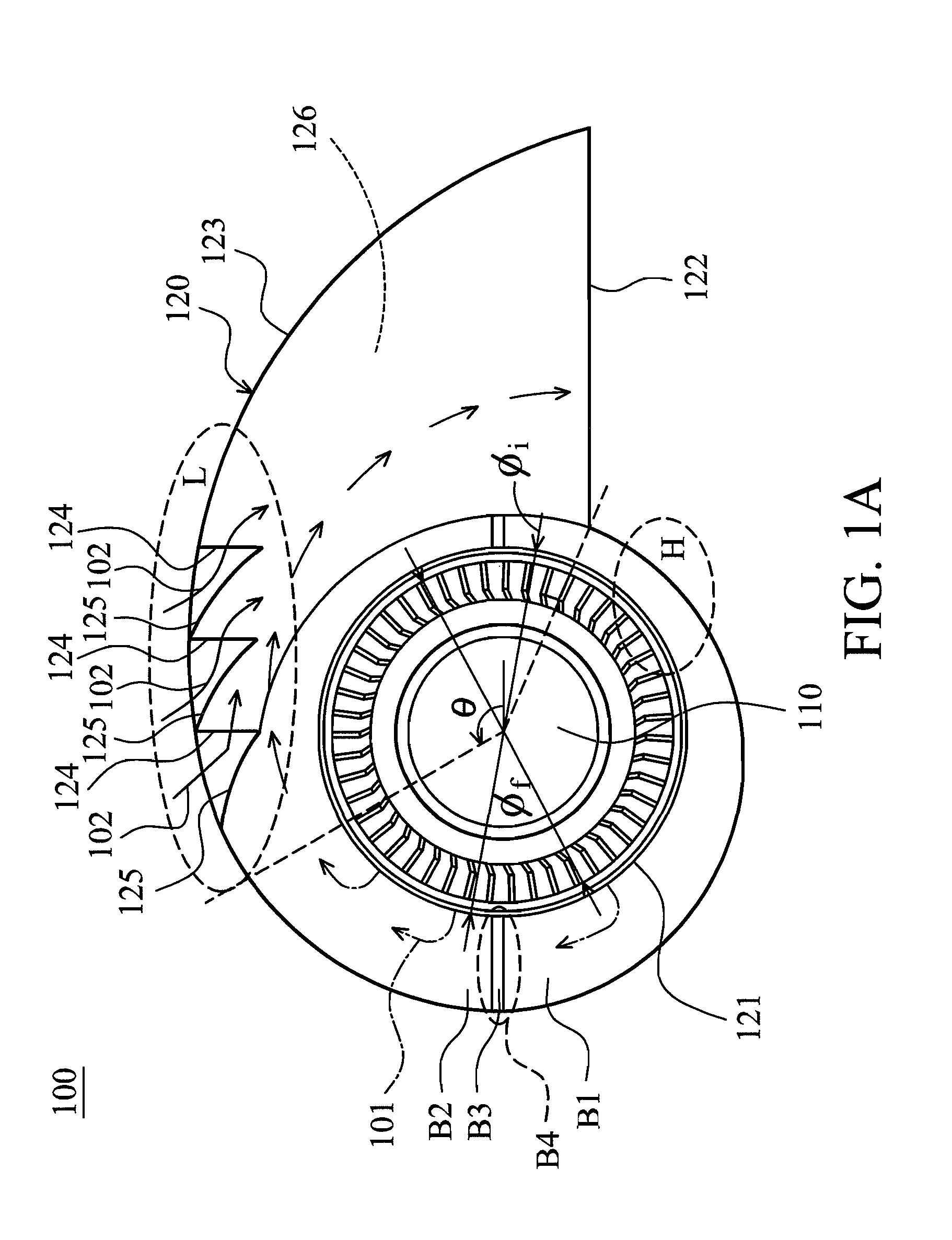
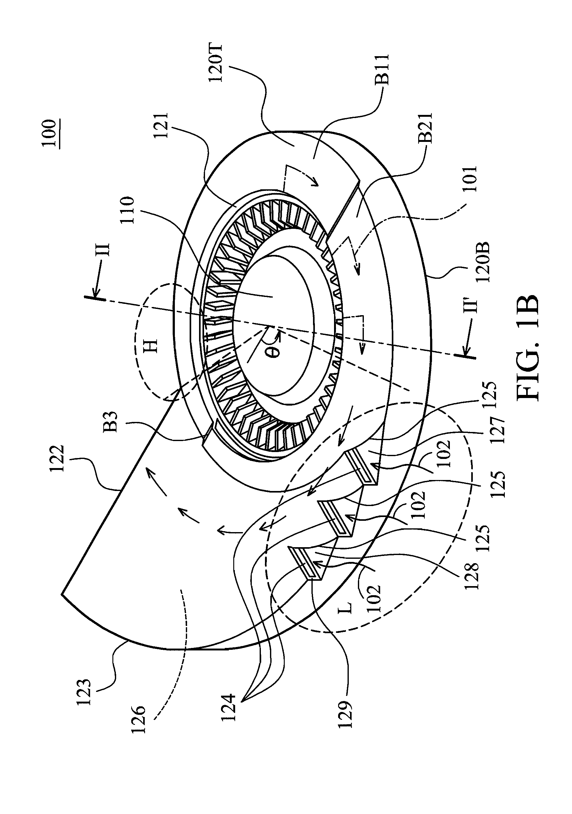
[0017]FIGS. 1A and 1B show a centrifugal fan 100 of an embodiment of the invention, including an impeller 110 and a housing 120. An inlet 121 and an outlet 122 are formed on the housing 120. The inlet 121 is perpendicular to the outlet 122. A flow path 126 communicates the inlet 121 to the outlet 122. The housing 120 includes an upper plate 120T, a lower plate 120B and a side wall 123. The impeller 110 is disposed in the inlet 121. At least one auxiliary inlet 124 is formed in a guiding groove 127 of the housing 120. The auxiliary inlets 124 face to the outlet 122. When the centrifugal fan 100 operates, a major flow 101 is impelled by the impeller 110, entering the hou...


PUM


Abstract

A centrifugal fan is provided. The centrifugal fan includes an impeller and a housing. The impeller has an impeller diameter. The housing includes an upper plate, a lower plate and a side wall, wherein the upper plate axially corresponds to the lower plate, a side wall is formed between the upper plate and the lower plate, an axial inlet is formed on the upper plate, a lateral outlet is formed on the side wall, the impeller is disposed in the housing and corresponds to the inlet, and a flow path communicates the inlet to the outlet, wherein a greatest width of the inlet is greater than or equal to the impeller diameter.

Description

CROSS REFERENCE TO RELATED APPLICATIONS[0001]This application claims the benefit of U.S. Provisional Application No. 61 / 536,344, filed Sep. 19, 2011, the entirety of which is incorporated by reference herein.BACKGROUND OF THE INVENTION[0002]1. Field of the Invention[0003]The present invention relates to a fan, and in particular relates to a centrifugal fan.[0004]2. Description of the Related Art[0005]Portable computers (for example, tablet computers or ultrabooks) are extremely thin, and the inner space therein is limited. The dimensions of the centrifugal fan disposed in the portable computer have decreased, and the space between the centrifugal fan and other elements inside of the portable computer has reduced. The heat dissipation effect of the centrifugal fan has therefore deteriorated. Particularly, with limited inner space, the input flow rate of the centrifugal fan has decreased, and the heat dissipation effect has worsened.BRIEF SUMMARY OF THE INVENTION[0006]In one embodimen...

Claims


Application Information

Patent Timeline
Patent Type & Authority Patents(United States)
IPC IPC(8): F04D29/42H01L23/467H05K7/20G06F1/20H01L23/427
CPCG06F1/203H01L23/467H05K7/20172H01L23/427H01L2924/0002H01L2924/00
Inventor LU, CHAO-WEN
Owner DELTA ELECTRONICS INC
Why Eureka
Try Eureka