Trolling motor

a technology of troll motor and troll rod, which is applied in the direction of marine propulsion, vessel parts, vessel construction, etc., can solve the problems of manual manipulation, high part count, and difficulty in implementation of above-mentioned stow/deploy/deploy and trim adjustment mechanisms, etc., and achieve the effect of low part coun

Active Publication Date: 2016-03-29
JOHNSON OUTDOORS
View PDF26 Cites 31 Cited by
  • Summary
  • Abstract
  • Description
  • Claims
  • Application Information

AI Technical Summary

Problems solved by technology

Due to the growing complexity and size of trolling motor systems in recent years, the aforementioned manually manipulated stow / deploy and trim adjustment mechanisms have become difficult if not infeasible to implement.
The increased weight and size of newer trolling motor designs essentially made manual manipulation undesirable.
While such systems have proven to be quite effective, current designs generally have a relatively complex design with a high part count.

Method used


Image

  • Trolling motor
  • Trolling motor
  • Trolling motor

Examples


Embodiment Construction

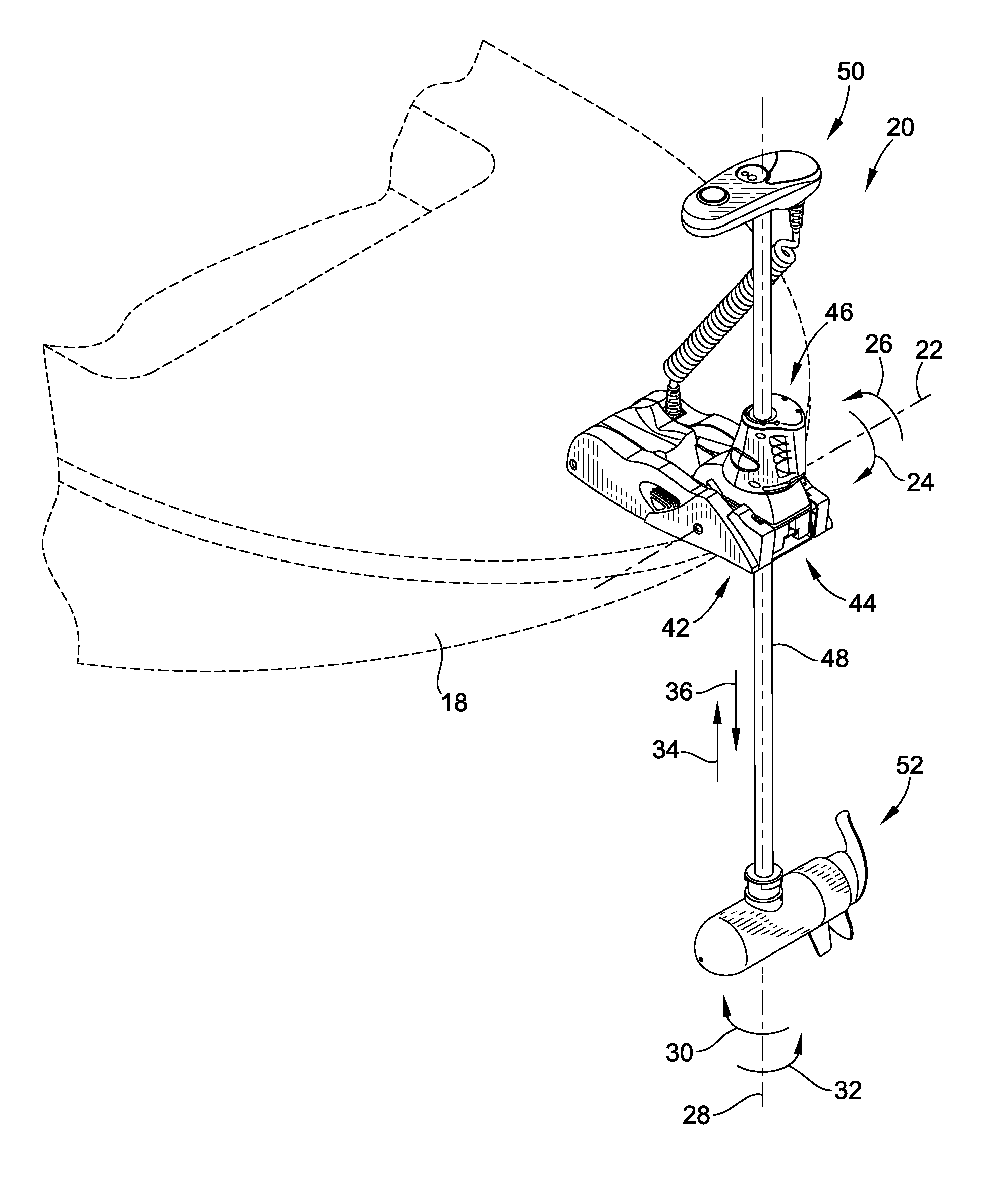
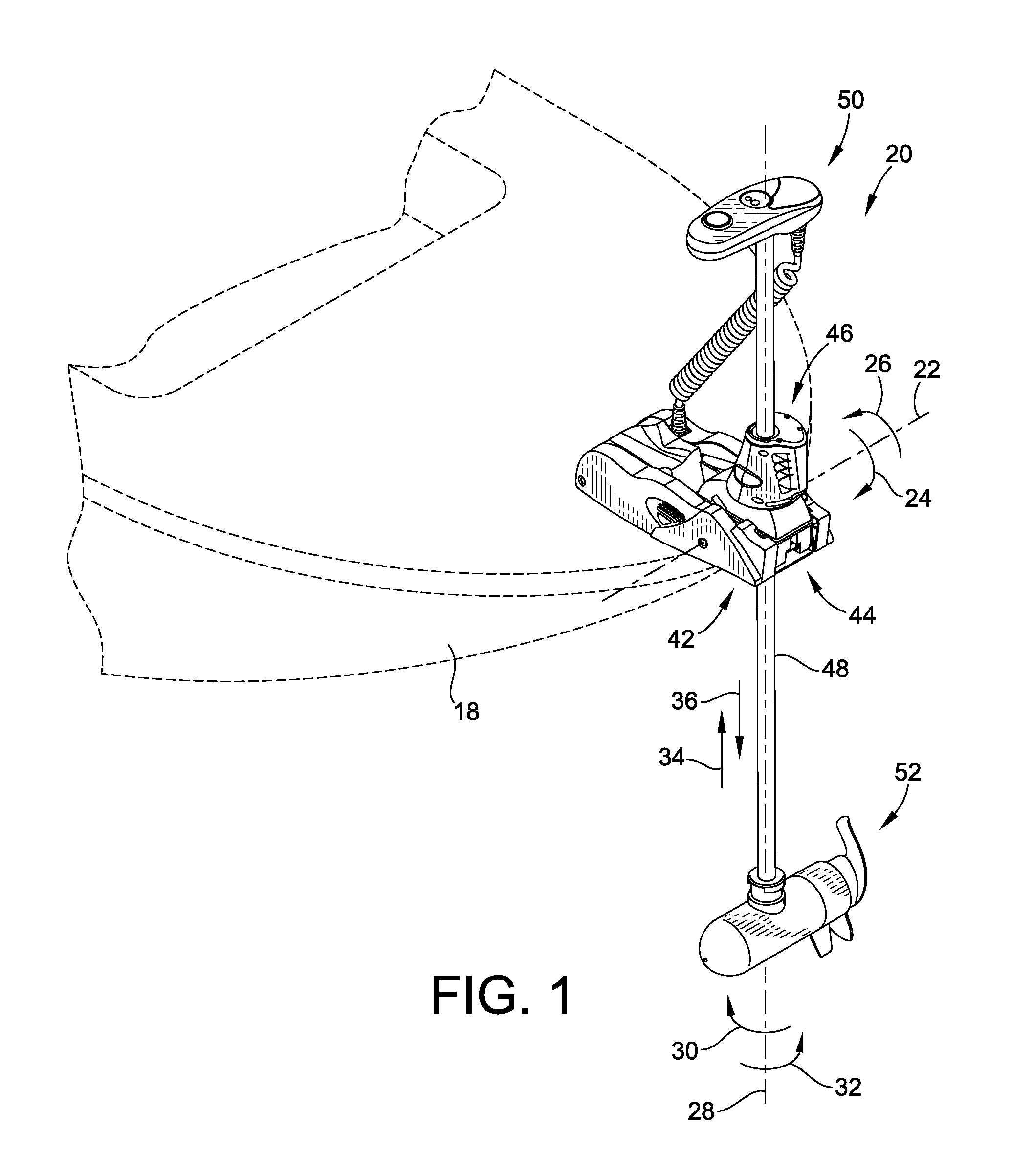
[0042]Turning now to the particular embodiment shown in the drawings, a trolling motor unit 20 is illustrated therein. With particular reference to FIG. 1, trolling motor 20 is shown mounted at the bow of a schematically represented watercraft 18. Trolling motor 20 is not in any way limited to any particular watercraft, and also may include various additional mounting brackets or the like were necessary for adequate mounting. Trolling motor 20 overcomes existing problems in the art by offering a trolling motor which provides a reduction of parts and complexity over contemporary systems relative to its stow / deploy, trim adjustment, and other features, while retaining the functionality thereof.

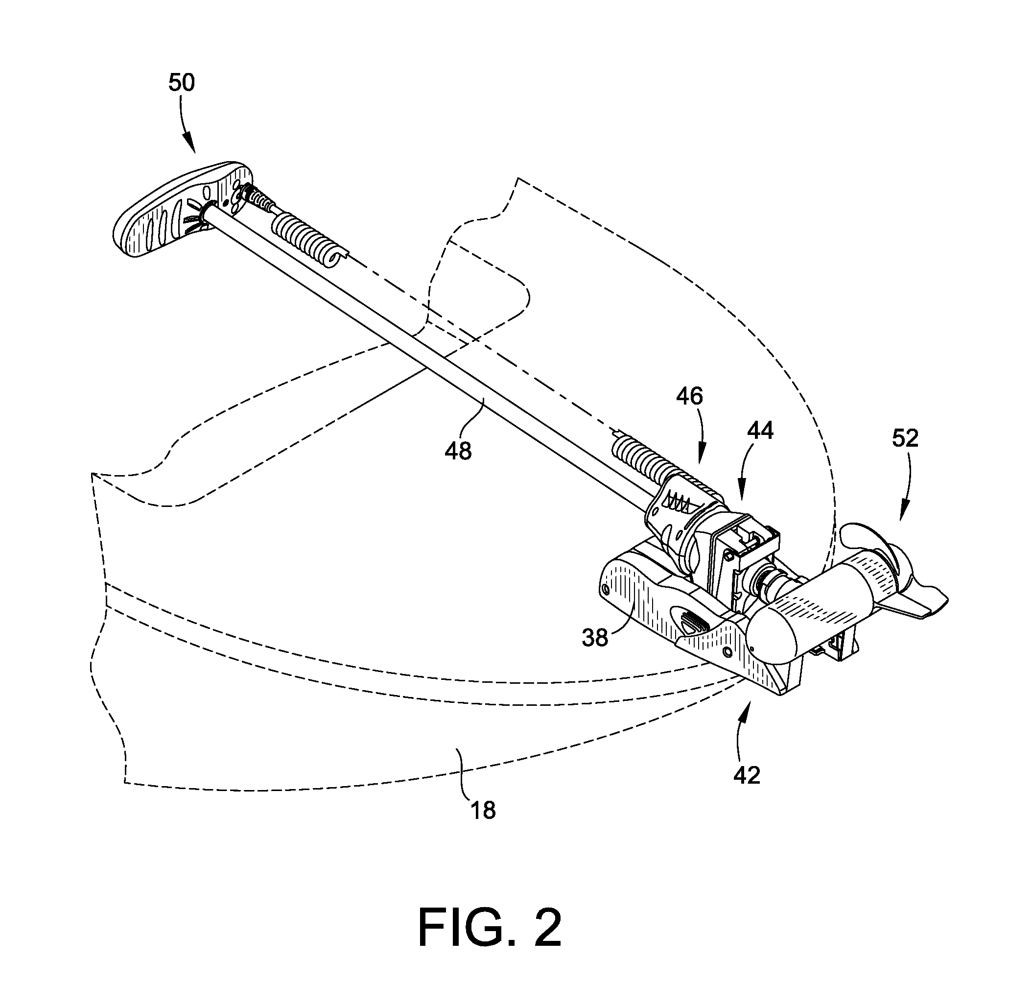
[0043]Still referring to FIG. 1, trolling motor unit 20 includes a base assembly 42 mounting trolling motor unit 20 to watercraft 18. Trolling motor unit 20 also includes a steering module 44 which effectuates the steering capabilities of trolling motor unit 20, a trim module 46 (also referred t...


PUM


Abstract

A trolling motor is provided. The trolling motor includes a base assembly with a steering module mounted to the base assembly. The steering module includes an internal drive arrangement for providing an output torque. The steering module also includes a trim module rotatably mounted to an upper portion of the steering module. A motor shaft assembly including a motor shaft, a head unit attached to an upper end of the motor shaft, and a motor power unit attached to a lower end of the motor shaft is also provided. The motor shaft extends through the base assembly, steering module, and trim module. A torque transfer arrangement is mounted between the trim module and the motor shaft of the motor shaft assembly for transferring the output torque provided by the steering module to the motor shaft to rotate the motor shaft assembly about a rotational steering axis.

Description

FIELD OF THE INVENTION[0001]This invention generally relates to watercraft equipment, and more particularly to trolling motors.BACKGROUND OF THE INVENTION[0002]Fishing boats and other vessels are often equipped with a trolling motor for providing a relatively small amount of thrust to slowly and quietly propel the boat or vessel. They advantageously provide for a finer adjustment of watercraft position than a main motor / propeller combination. Typically, the trolling motor is powered electrically using a boat's existing electrical power source, or a stand-alone electrical power source which in either case is most often a battery. Examples of a contemporary trolling motor may be found at U.S. Pat. Nos. 6,325,685 and 6,369,542 to Knight et al., the entire teachings and disclosures of which are incorporated by reference herein.[0003]Trolling motors remain a viable and sought after apparatus for various applications, including but not limited to fishing, recreation, and commercial applic...

Claims


Application Information

Patent Timeline
Patent Type & Authority Patents(United States)
IPC IPC(8): B63H20/00B63H5/125B63H21/17B63H23/02
CPCB63H20/007B63H5/125B63H21/17B63H2023/0291
Inventor BERNLOEHR, DARREL, A.TUREK, CRAIG, E.SCHUMANN, MATTHEW, P.
Owner JOHNSON OUTDOORS
Why Eureka
Try Eureka