Fuel rail made of a plastic material with a heating system

a technology of fuel rails and plastic materials, which is applied in the direction of liquid fuel feeders, machines/engines, electric control, etc., can solve the problems of high specific vaporization heat, high corrosiveness, and high production costs of assembly, so as to reduce costs, improve spatial arrangement of elements, and the effect of the same functional characteristics

Active Publication Date: 2016-04-05
ROBERTBOSCH LTDA
View PDF16 Cites 9 Cited by
  • Summary
  • Abstract
  • Description
  • Claims
  • Application Information

AI Technical Summary

Benefits of technology

[0009]The present invention refers to a set which constitutes a fuel rail made of plastic material with a heating system. The said rail is applied, mainly, in devices for aiding the cold start of engines which consume fuels whose specific vaporization heat is high, for example, alcohol. The fuel rail made of plastic material with a heating system presents a reduced cost and the same functional characteristics if compared to the metal fuel rails with heating systems known by the state of the art. Further, the said fuel rail is made of plastic material with a heating system that presents an improved spatial arrangement of its elements, where its external shape and the internal compartments are configured in such a manner, that slide pins employed in the plastic injection process can easily be removed as a function of the absence of negative faces.

Problems solved by technology

This is due to the fact that alcohol presents a high specific vaporization heat when compared to gasoline.
This is due to the fact that alcohol is highly corrosive.
The fact that the ducts are made of metal elevates the production costs for the assembly, as well as, contributing to an increase in the vehicles weight.
This change presents, however, some drawbacks for its implementation.
A second difficulty is linked to the confection of the rail with a single piece of plastic material with a mold that allows maintaining its complex geometry resulting from its functional characteristics known by the state of the art and that, at the same time, allows a rapid and economical plastic injection process.
Such type of rail can be seen in document US 2009 / 199822 A1 which comprises different parts to be assembled together (which comprises security due to leakage of fuel) and also does not guarantee proper start-up of an engine when heating the fuel since due to its geometry will have to heat all the fuel inside the rail.
Otherwise, a later fitting of several components must be undertaken, which can result in a loss of the confiability of the rail.
In the metal rails of the state of the art, what increases their total cost is the connection of its main external elements, constituted by a main tube and by two secondary ducts.
The shape of the heated rail of the state of the art can, therefore, interfere in the standard layout of an engine, eventually creating obstacles to its installation in the assembly line due to the difficulty of access for tools.

Method used


Image

  • Fuel rail made of a plastic material with a heating system
  • Fuel rail made of a plastic material with a heating system
  • Fuel rail made of a plastic material with a heating system

Examples


first embodiment

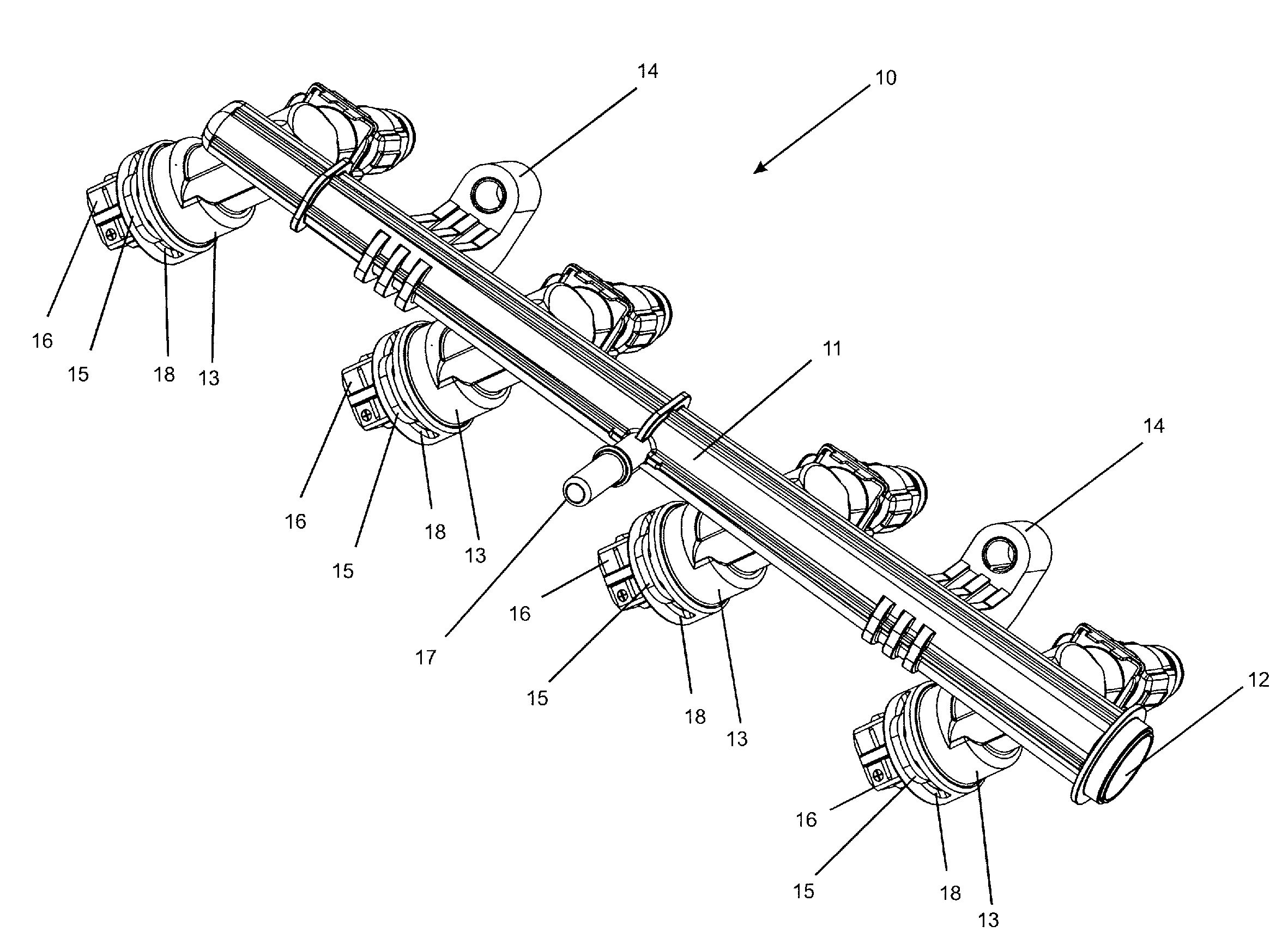
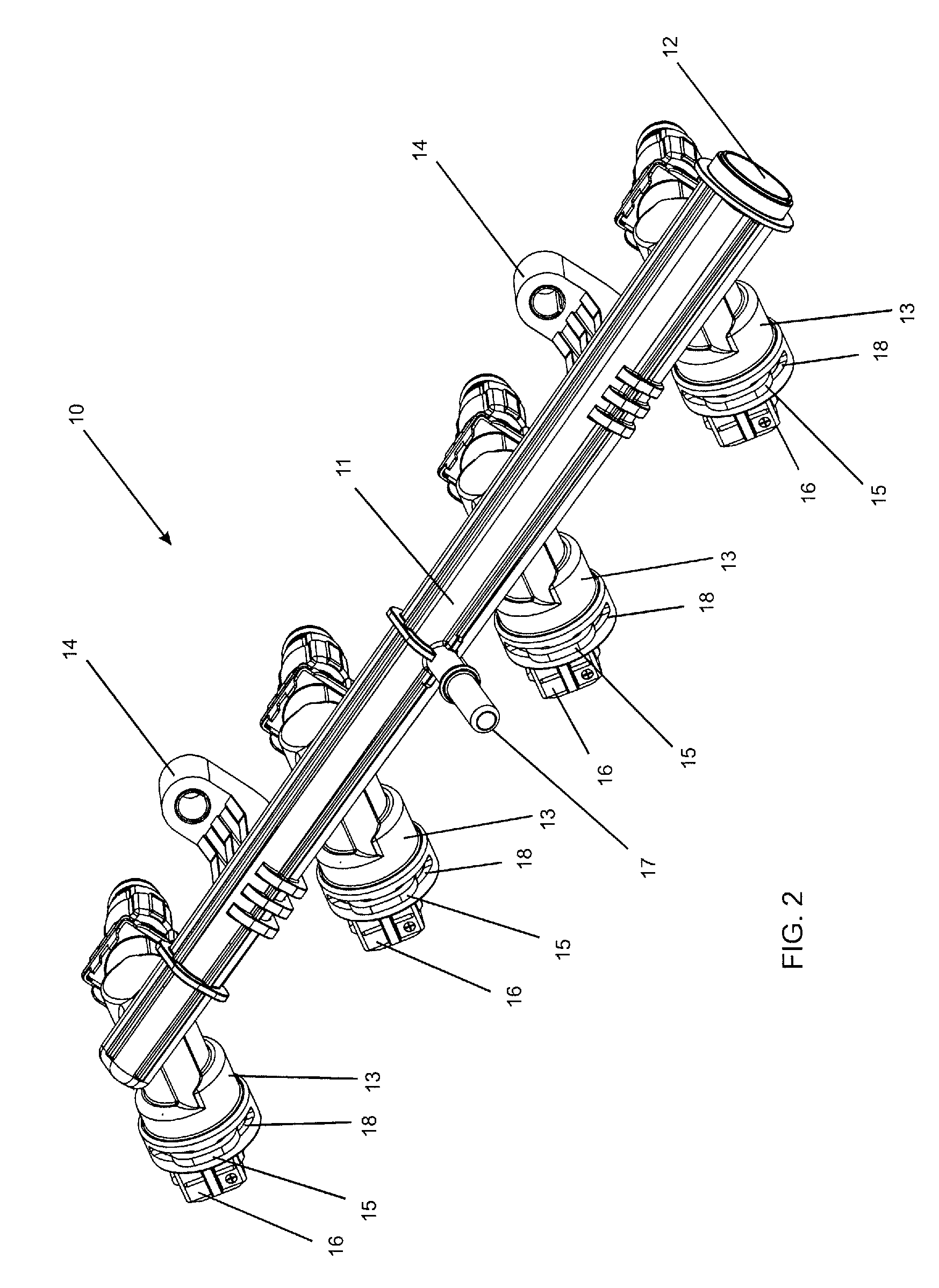
[0036]FIG. 6 presents a view of the fuel rail made of plastic material with a heating system 10 that shows the upper secondary duct 13 in detail. In the present invention, the surface 61, where the exit of the internal duct 38 or internal ducts 38 occurs, is flat, that is, the flow of fuel as it reaches the end of the internal duct 38 will distribute itself in a uniform manner throughout the base of the heating element 16.

second embodiment

[0037]FIG. 7 presents a view of a fuel rail made of plastic material with a heating system 100 which shows the upper secondary duct 13 in detail. In the present invention, the surface 71, where the exit of the internal duct 38 occurs, presents a recess 72, which permits that the flow of fuel in reaching the end of the internal duct 38 be directed, through the said recess 72, to a lower portion of the base of the heating element 16. This makes the process of heating the fuel optimized, bearing in mind that it involves the lance 4 of the heating element 16, travel-ling along a longer route and in this manner increasing the contact time between the fuel and the said lance 4, which is responsible of the transmission of heat. The recess 72 can also exist on both sides of the surface 71, that is, on the left and right sides in order to optimize even further the trajectory of the flow of fuel.


PUM


Abstract

The present invention refers to a fuel rail made of plastic material with a heating system (10,100). The said rail is applied, mainly, in the form of devices for aiding the cold start of engines which consume fuels whose specific vaporization heat is high, for example, alcohol. The fuel rail made of plastic material with a heating system presents reduced cost and weight and the same functional characteristics if compared to the fuel rails known by the state of the art, which are usually made of metal. Furthermore, the said fuel rail made of plastic material with a heating system presents internal compartments configured in such a manner that the sliders containing slide pins (51, 52, 53) of the injection mold can be easily removed, since there is no formation of negative faces.

Description

BACKGROUND OF THE INVENTION[0001]The present invention refers to an assembly which is constituted by a fuel rail made of plastic material with a heating system. The said rail is employed in cold start auxiliary devices of internal combustion engines which consume fuels with an elevated specific vaporization heat, for example, alcohol.[0002]In the last few years a great popularization of vehicles that use simultaneously more than one fuel has occurred, for example, gasoline and alcohol / ethanol. These vehicles, when they operate with alcohol as fuel, usually need an additional fuel tank dedicated to an initial injection of gasoline in order to start in cold climates. This is due to the fact that alcohol presents a high specific vaporization heat when compared to gasoline. Based on this physical-chemical limitation of alcohol and with the objective of eliminating the additional gasoline tank, vehicle manufacturers have developed cold starting devices for alcohol which aid the combustio...

Claims


Application Information

Patent Timeline
Patent Type & Authority Patents(United States)
IPC IPC(8): F02M53/06F02M53/02F02M69/46F02M55/02F02M61/16F02D41/06F02D41/04F02D41/00
CPCF02M53/02F02M55/025F02M61/166F02M53/06F02M69/465F02D41/0025F02D41/047F02D41/064F02D2200/0606F02M2200/60F02M2200/9015F02M2200/95
Inventor MOREIRA COLETTO, TULIO ITALICOLEPSCH, FERNANDOVASCONCELOS, ALVARO AUGUSTO
Owner ROBERTBOSCH LTDA
Why Eureka
Try Eureka