
Spectrum measurement device

a technology of spectral measurement and measurement target, which is applied in the direction of distance measurement, scene recognition, instruments, etc., can solve the problems of reducing recognition accuracy, reducing recognition accuracy, and changing the spectral of the measurement targ

Active Publication Date: 2016-04-05
TOYOTA JIDOSHA KK +1
View PDF60 Cites 4 Cited by
  • Summary
  • Abstract
  • Description
  • Claims
  • Application Information

AI Technical Summary

Benefits of technology

This patent is about a spectrum measurement device that uses a spectral sensor to recognize measurement targets with high reliability despite the influence of ambient light. The device detects the spectral data of the observed light and finds the reflectance specific to the measurement target, which is correlated to the light intensity of the lighting device. By comparing the observed spectral data with database entries, the device can identify the type of measurement target with high accuracy. This reduces the need for correction calculations and improves the reliability of recognizing the measurement target. The distance between the observation point and the measurement target can also be accurately determined, allowing for better target recognition. Overall, this device provides accurate and reliable recognition information with minimal influence of ambient light.

Problems solved by technology

When recognizing various measurement targets using such a spectral sensor, one issue is that the spectrum of the measurement target changes by the influence of ambient light such as sunlight.
Even if spectral data on a measurement target can be obtained using the spectral sensor, a reduction in recognition accuracy by the influence of such ambient light is inevitable.
Namely, the reduction in recognition accuracy due to the influence of ambient light deters an attempt to recognize various measurement targets in the vicinity of the vehicle using spectral data taken by the spectral sensor, and makes it difficult to recognize measurement targets, which is required particularly in assisting the drive of the vehicle.

Method used


Image

  • Spectrum measurement device
  • Spectrum measurement device
  • Spectrum measurement device

Examples


first embodiment

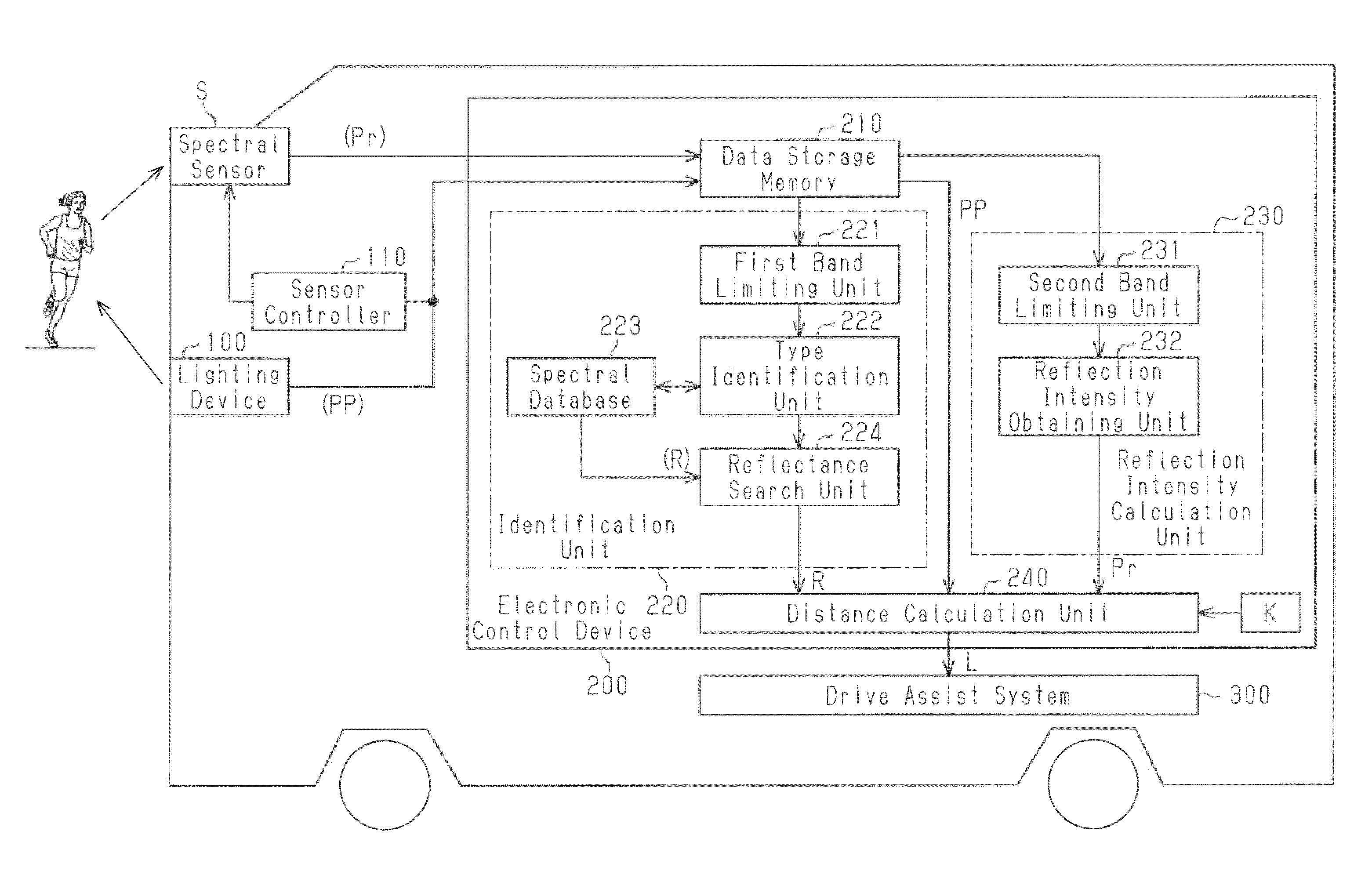
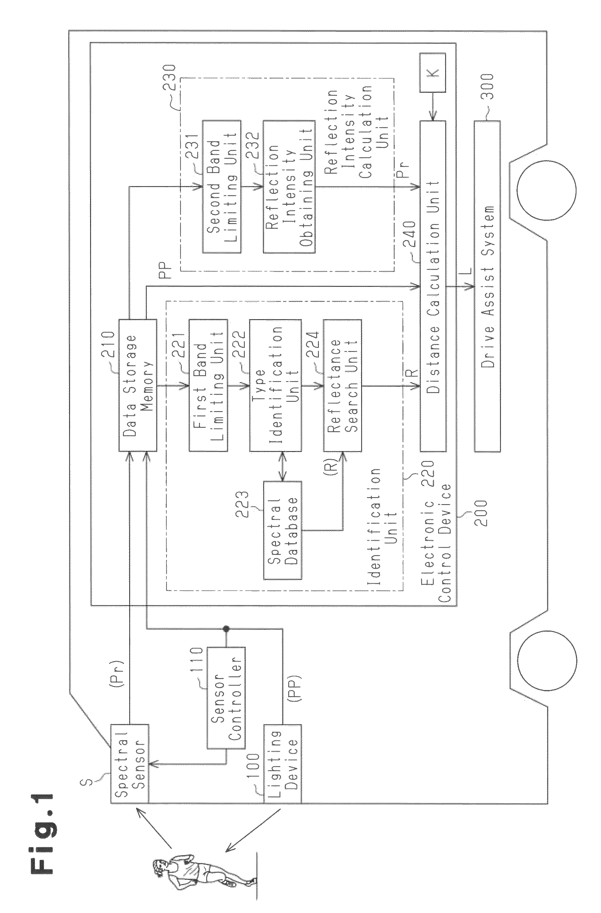
[0045]FIG. 1 illustrates the schematic configuration of a spectrum measurement device according to the present invention.

[0046]As shown in FIG. 1, the spectrum measurement device of this embodiment is mounted on a vehicle such as an automobile, for example, and includes a lighting device 100 capable of irradiating light of both wavelength bands having a high atmospheric absorption coefficient and a low atmospheric absorption coefficient to measurement targets that are objects such as pedestrians, traffic lights, or obstacles. The spectrum measurement device also includes a spectral sensor S for observation of spectral data on a measurement target irradiated by the lighting device 100. The spectrum measurement device further includes a sensor controller 110 that controls the light sensitivity or the like of the spectral sensor S. In this embodiment, the measurement target that is an object present in the vicinity of the vehicle is identified as one of the objects such as a human bein...

second embodiment

[0094]In the second embodiment described above, changes over time of spectral data are determined through difference operation on spectral data obtained at various different points in time. Alternatively, the changes over time of spectral data may be determined through division operation on spectral data obtained at various different points in time. In this case, the quotient Sw, which indicates a change over time in spectral data, is calculated by the following expression (3), where S and S+1 respectively represent the spectral intensity of spectral data obtained and extracted at different points in time t and t+1.

Sw=S(t+1) / S(t).  (3)

[0095]It is then determined that the measurement target is approaching the vehicle if the quotient Sw exceeds “1”, and that the measurement target is going away from the vehicle if the quotient Sw is less than 1. If the quotient Sw is 1, it is determined that the relative distance from the measurement target to the vehicle is constant.

[0096]In the seco...


PUM


Abstract

A spectrum measurement device that recognizes objects to be measured on the basis of spectral data of observed light that is detected by a spectrum sensor capable of measuring wavelength information and light intensity information. The spectrum measurement device comprises a lighting device capable of projecting light that includes a wavelength region with a high atmospheric absorption index and recognizes the distance from a vehicle to an object to be measured through a computation that uses spectral data of observed light that is obtained from the object to be measured whereupon light of at least the wavelength region with the high atmospheric absorption index is projected.

Description

FIELD OF THE INVENTION[0001]The present invention relates to a spectrum measurement device that recognizes a measurement target from a set of spectral data on the measurement target measured by a spectral sensor.BACKGROUND OF THE INVENTION[0002]Some vehicles such as automobiles in recent years include a drive assist system mounted thereon that recognizes the dynamically changing situation around the vehicle including pedestrians and traffic lights so as to assist the driver to drive the vehicle or to make decisions. Most of such drive assist systems take an image of a traffic light or a pedestrian with a CCD camera or the like, recognize the condition of the traffic light or pedestrian through image processing of the taken image, and use the recognized results in assisting the drive as mentioned above. However, a pedestrian typically varies numerously in shape depending on the size, orientation, or presence or absence of an object being carried therewith, so that it is difficult to ...

Claims


Application Information

Patent Timeline
Patent Type & Authority Patents(United States)
IPC IPC(8): G01C3/08G01S17/93G06K9/00G06K9/20G08G1/16G01S17/931G06V10/143
CPCG06K9/00805G01S17/936G06K9/2018G08G1/165G08G1/166G01S17/931G06V20/58G06V10/143
Inventor FUNAYAMA, RYUJIKAWAMATA, SHINYAYOSHIKAWA, YUMIKOISHI, TSUTOMU
Owner TOYOTA JIDOSHA KK
Learn More