Supercharge Your Innovation With Domain-Expert AI Agents!

Light emitting device with reflective electrode

a light-emitting device and reflective electrode technology, which is applied in semiconductor devices, semiconductor/solid-state device details, electrical apparatuses, etc., can solve the problems of increasing the current applied to the light-emitting diode, increasing the resistance, and reducing the light-emitting efficiency of the light-emitting diod

Active Publication Date: 2016-04-05
EPISTAR CORP
View PDF11 Cites 1 Cited by
  • Summary
  • Abstract
  • Description
  • Claims
  • Application Information

AI Technical Summary

Benefits of technology

The multi-metal barrier layer effectively prevents material migration and reaction, maintaining high light extraction efficiency and electrode conductivity even under high current conditions, extending the device's operational lifespan.

Problems solved by technology

The migration of the material of the mirror layer causes the increase of the resistance of electrode and lowers the light-emitting efficiency of the light-emitting diode.
Nevertheless, in recent years, as the light from a single chip is required to emit more, the electrical current applied to the light-emitting diode is increased, and the large electrical current may destroy the barrier layer 11.
But, it is not easy to form a barrier layer 11 which has a uniform thickness on the mirror layer 12.

Method used


Image

  • Light emitting device with reflective electrode
  • Light emitting device with reflective electrode
  • Light emitting device with reflective electrode

Examples


Embodiment Construction

[0015]Exemplary embodiments of the present application will be described in detail with reference to the accompanying drawings hereafter. The following embodiments are given by way of illustration to help those skilled in the art fully understand the spirit of the present application. Hence, it should be noted that the present application is not limited to the embodiments herein and can be realized by various forms. Further, the drawings are not precise scale and components may be exaggerated in view of width, thickness, length, etc. Herein, the similar or identical reference numerals will denote the similar or identical components throughout the drawings.

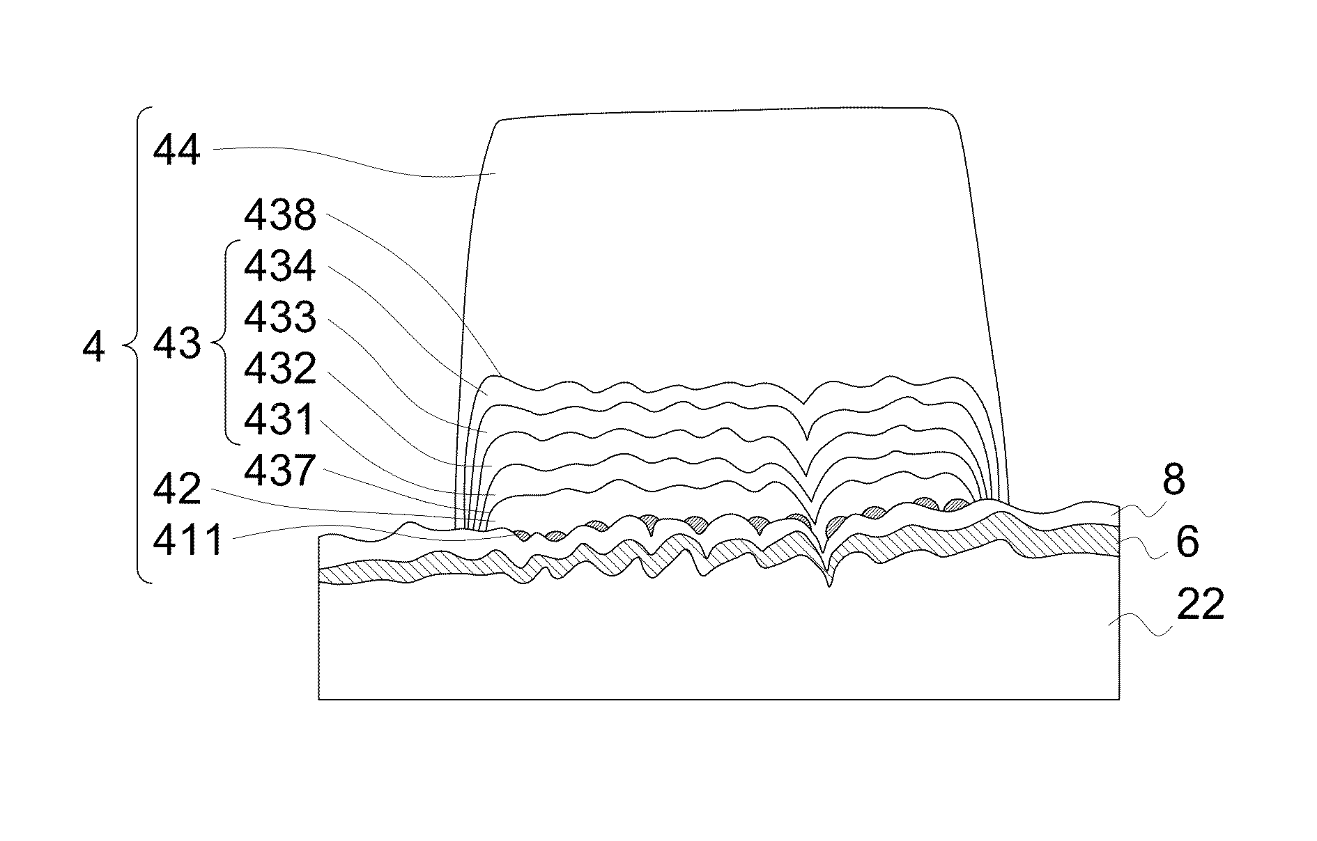
[0016]FIG. 3A shows the cross-sectional diagram of a light-emitting diode 1 with electrodes and FIG. 3B shows the detail structure of the electrode on the light-emitting diode according to the first embodiment of the present application. The light-emitting diode 1 has electrodes 4 on the semiconductor light emitting stack 2. The se...


PUM


Abstract

A light-emitting device includes a semiconductor light emitting stack and an electrode on the semiconductor light emitting stack, wherein the electrode includes a mirror layer, an adhesion layer inserted between the mirror layer and the semiconductor light emitting stack, a bonding layer, and a barrier layer inserted between the mirror layer and the bonding layer and covering the mirror layer to prevent the mirror layer from reacting with the bonding layer, wherein the barrier layer includes a first pair of different metals.

Description

TECHNICAL FIELD[0001]The present application relates to a light-emitting device with a reflective electrode, and a method to manufacture the same.DESCRIPTION OF BACKGROUND ART[0002]As the light-emitting efficiency is increased and the cost of manufacturing is decreased, the dream for solid lighting device to replace the traditional lighting device may come true in recent years. Currently, the inner light-emitting efficiency of the light-emitting diode is about 50% to 80%, but a part of the light may be absorbed by the electrode or the light-emitting layer so the total light-emitting efficiency is degraded. Therefore, the mirror layer under the electrode has been provided to solve the problem. When the route of the light extracted from the light-emitting layer is blocked by the electrode, the mirror can reflect but not absorbs the light.[0003]When the electrical current is applied into the light-emitting diode and flows through the electrode, the material of the mirror layer may be m...

Claims


Application Information

Patent Timeline
Patent Type & Authority Patents(United States)
IPC IPC(8): H01L23/48H01L33/40H01L29/40H01L23/52H01L33/44
CPCH01L33/40H01L33/405H01L33/44H01L2933/0016H01L33/38H01L33/22
Inventor KO, TING-CHIAKUO, DE-SHANCHUNG, CHIEN-KAIKO, TSUN-KAI
Owner EPISTAR CORP
Features
  • R&D
  • Intellectual Property
  • Life Sciences
  • Materials
  • Tech Scout
  • Unparalleled Data Quality
  • Higher Quality Content
  • 60% Fewer Hallucinations
Learn More