Light emitting device driver circuit and control circuit and control method thereof
a technology of light emitting devices and driver circuits, which is applied in the direction of lighting devices, electrical devices, light sources, etc., can solve the problems of limited dimming range of led circuits b>20/b>, insufficient latching current and holding current of triac devices, and misfire still occurring,
- Summary
- Abstract
- Description
- Claims
- Application Information
AI Technical Summary
Benefits of technology
Problems solved by technology
Method used
Image
Examples
first embodiment
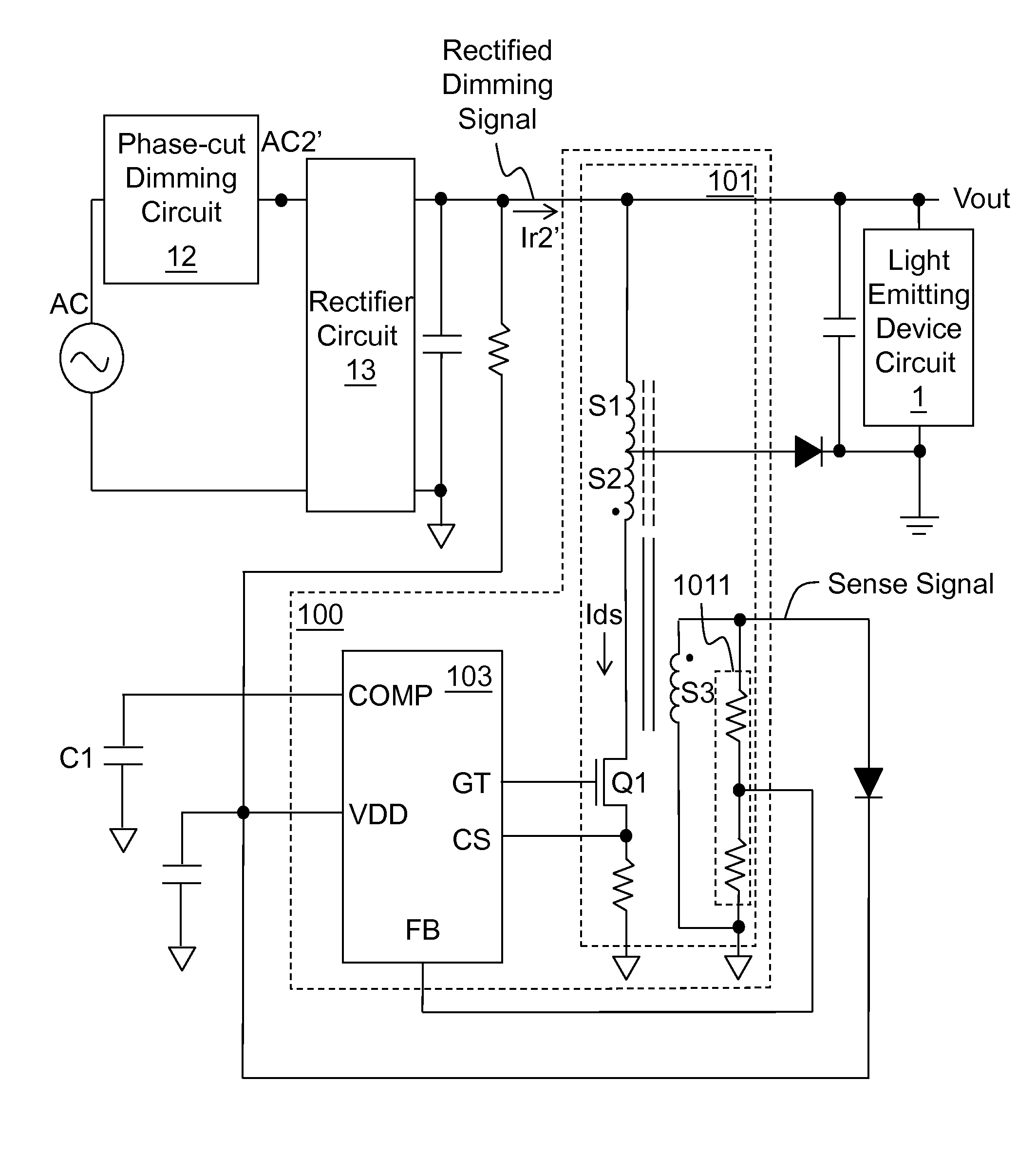
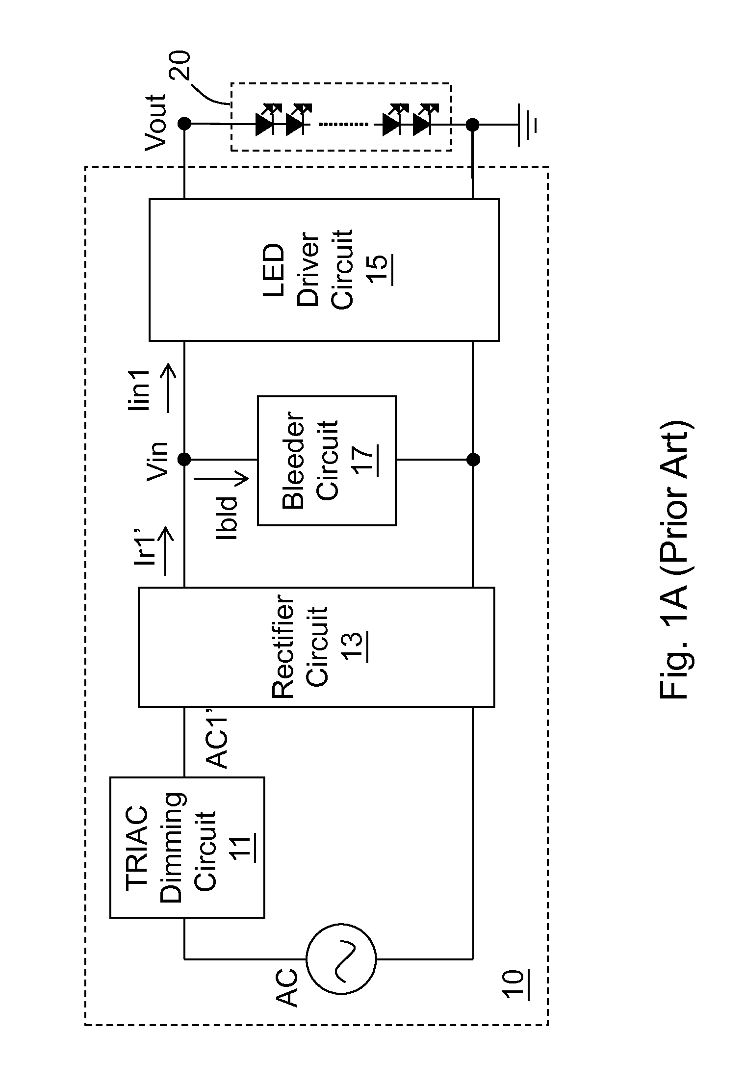
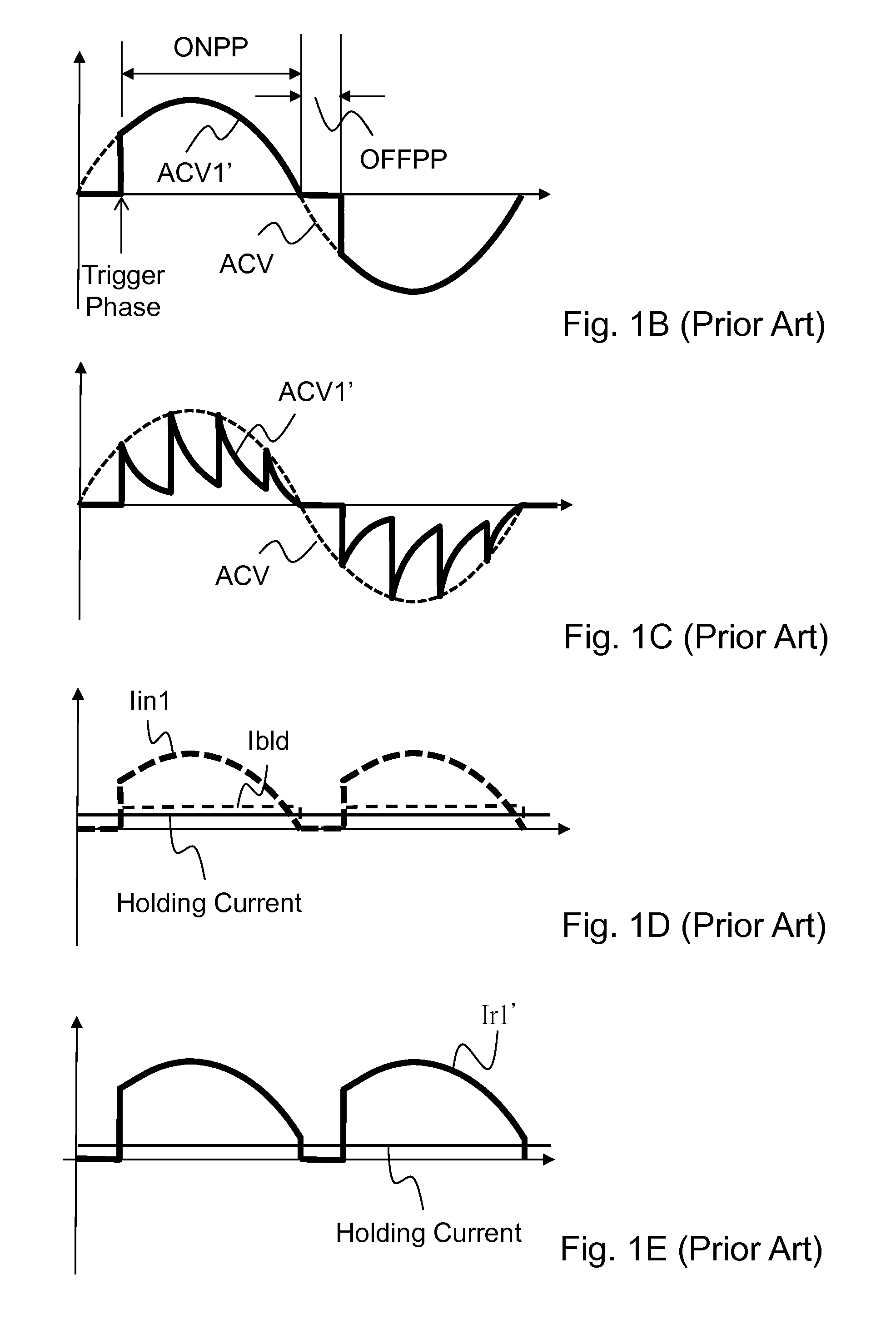
[0037]FIGS. 2A-2C show the present invention. As shown in FIG. 2A, alight emitting device driver circuit 100 drives a light emitting device circuit 1 according to a rectified dimming signal. A phase-cut dimming circuit 12 converts an AC signal to an AC dimming signal AC2′, wherein the phase-cut dimming circuit 12 is for example but not limited to the prior art TRIAC dimming circuit 11. The AC dimming signal AC2′ includes an AC dimming current flowing through the phase-cut dimming circuit 12. The phase-cut dimming circuit 12 blocks an OFF phase period OFFPP of the AC signal (as shown by the prior art OFF phase period OFFPP), and retains an ON phase period ONPP (as shown by the prior art ON phase period ONPP) of the AC signal, to generate the AC dimming signal AC2′. The rectifier circuit 13 converts the AC dimming signal AC2′ to the rectified dimming signal, wherein the rectifier circuit 13 is for example but not limited to abridge rectifier circuit, and the rectifier circuit 13 can o...
second embodiment
[0042]FIG. 3 shows the present invention. This embodiment shows a more specific embodiment of the light emitting device driver circuit 100. As shown in the figure, the power stage circuit 101 for example includes a first winding S1, a second winding S2, a third winding S3, and a power switch Q1. The first winding S1 is coupled to the rectifier circuit 13 and the power switch Q1, for receiving the rectified dimming signal and determining a switch current Ids flowing through the power switch Q1 according to the operation of the power switch Q1. The second winding S2 is coupled to the first winding S1, for generating the output signal including the output voltage Vout which is provided to the light emitting device circuit 1, according to the rectified dimming signal and the switch current Ids. The third winding S3 is coupled to the second winding S2, for generating a sense signal according to the output signal. As shown in the figure, in one non-limiting embodiment, the first winding S...
third embodiment
[0044]FIG. 4A shows the present invention. This embodiment shows a more specific embodiment of the control circuit 103. As shown in FIG. 4A, the control circuit 103 includes a pulse width modulation (PWM) circuit 1031, a current limit (CL) circuit 1033, and a determination circuit 1035. The PWM circuit 1031 is for generating a PWM signal according to a level of the feedback signal FB. The CL circuit 1033 is for generating a CL signal according to whether the current sense signal CS reaches a predetermined current threshold PCL. The determination circuit 1035 is coupled to the PWM circuit 1031 and the CL circuit 1033, for generating an operation signal GT according to the PWM signal and the CL signal, wherein the determination circuit 1035 determines the duty of the operation signal GT according to one of the PWM signal and the CL signal. The power stage circuit 101 operates the power switch Q1 according to the operation signal GT to maintain the absolute level of the AC dimming curr...
PUM
 Abstract
Description
Claims
Application Information
 - R&D
- Intellectual Property
- Life Sciences
- Materials
- Tech Scout
- Unparalleled Data Quality
- Higher Quality Content
- 60% Fewer Hallucinations
Browse by: Latest US Patents, China's latest patents, Technical Efficacy Thesaurus, Application Domain, Technology Topic, Popular Technical Reports.
© 2025 PatSnap. All rights reserved.Legal|Privacy policy|Modern Slavery Act Transparency Statement|Sitemap|About US| Contact US: help@patsnap.com


