Internal power supply control device having at least one lighting control device for a motor vehicle

a technology of motor vehicles and control devices, which is applied in the testing instruments, transportation and packaging, etc., can solve the problems of difficult monitoring of individual semiconductor devices, low current breakage amperage, and easy interpretation of errors in the lower amperage of current breakage, so as to reduce production costs

Active Publication Date: 2016-04-12
AUTOMOTIVE LIGHTING REUTLINGEN GMBH
View PDF40 Cites 0 Cited by
  • Summary
  • Abstract
  • Description
  • Claims
  • Application Information

AI Technical Summary

Benefits of technology

[0021]By this, power-supply control devices, identical in terms of their hardware and differing only in terms of software, are suitable for both the operation of incandescent lamps as well as far an energy-efficient operation of semiconductor light sources.
[0023]In this manner, an operation and a monitoring of the semiconductor light source through the use of the normal monitoring of the current flow through the connection pin of the power-supply control device are possible. For this, there is no need to alter the hardware in the known power-supply control devices. All that is needed is an additional connection pin of the power-supply control device to be allocated to each light-control device. This, however, is not problematic because conventional power-supply control devices exhibit a sufficient number of unused connection pins and are, furthermore, equipped for monitoring the current flows through these connection pins.
[0024]As a result, the necessary electrical supplementary loads previously used in light-control devices by which prior excess electric energy is converted to heat can be eliminated. Thus, the previously necessary supplementary structures for the dissipation of excess heat can also be eliminated. In this manner, installation space and weight, which were previously necessary for accommodating the larger cooling structures, can be eliminated. An unnecessary current flow amounting to the aforementioned 200 mA generates an electrical power of 3.2 W in a typical motor-vehicle power supply of 16 V, which must be converted to heat in the related art. Through the elimination of this heat, the invention enables the possibility of replacing a heat-conducting metal housing of the light-control device with a lighter and less expensive plastic housing. By this, the production costs can also be reduced.

Problems solved by technology

Difficulties in the monitoring thereof occur from the specified differences in the activation of such lamps.
It is also problematic that semiconductor light sources are frequently operated with a pulse-width-modulated current instead of a continuously flowing current.
When the power-supply control device then maps the pulse-width-modulated signal during a current break, the lower amperage of the current break could be easily interpreted as an error because low values of this type also occur, for example, during a power failure.
This approach has disadvantages in the form of an unnecessarily high power consumption.
From the necessity of having to discharge larger quantities of heat as well, there is the additional disadvantage that numerous heat-sink volumes and surfaces are required than would be needed with a more energy-efficient system.

Method used


Image

  • Internal power supply control device having at least one lighting control device for a motor vehicle
  • Internal power supply control device having at least one lighting control device for a motor vehicle
  • Internal power supply control device having at least one lighting control device for a motor vehicle

Examples


Embodiment Construction

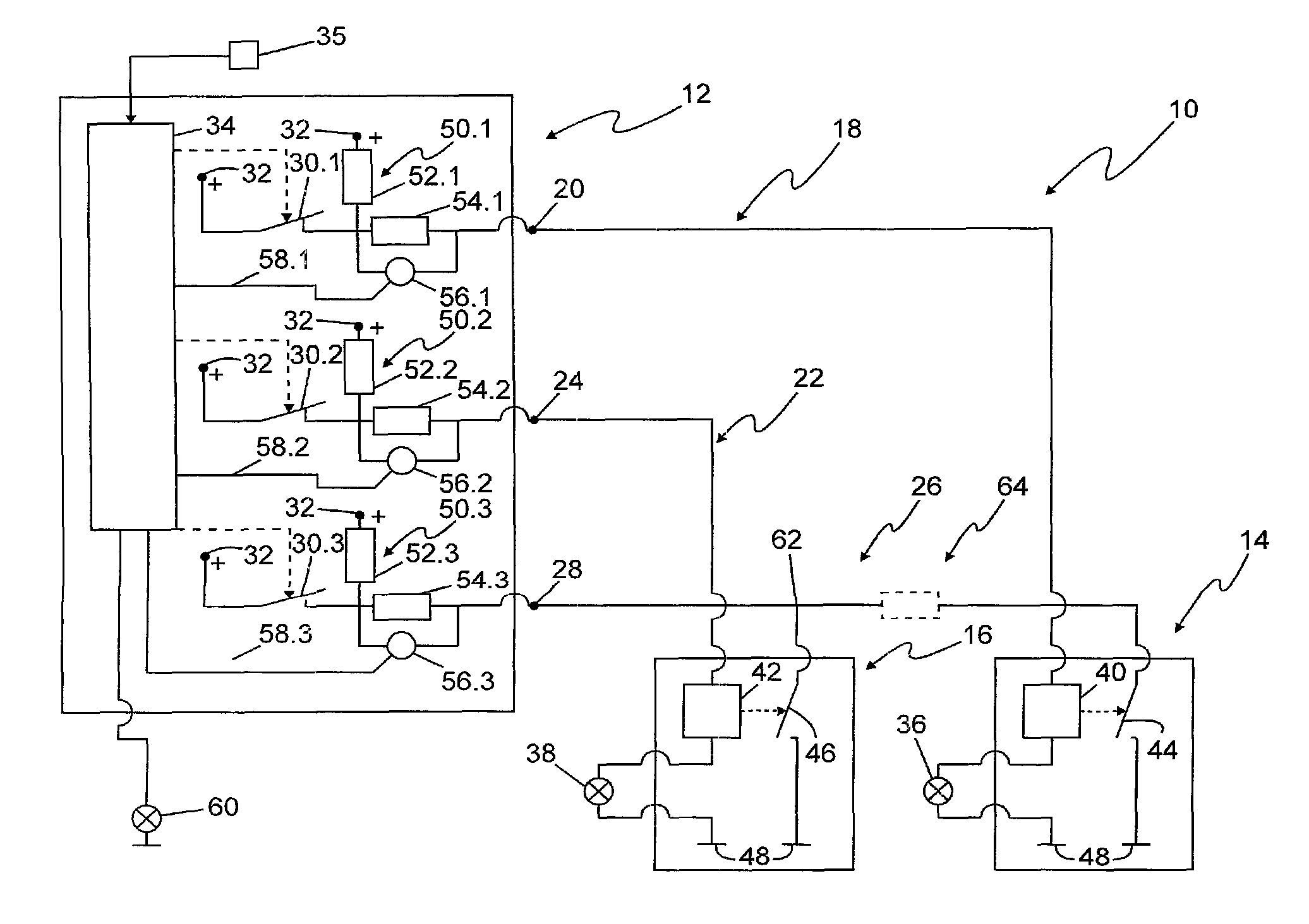
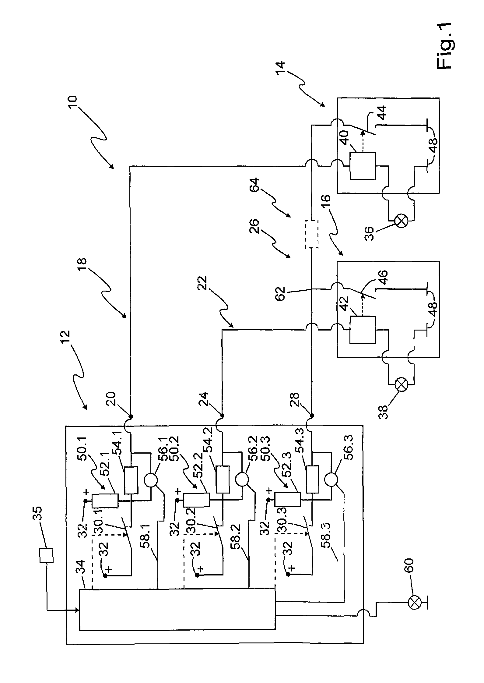
[0028]Identical reference symbols in the figures indicate, in each case, identical elements or elements with identical functions. In detail, FIG. 1 shows a combination of a power-supply control device 12 of a motor vehicle, a first light-control device 14, and a second light-control device 16. The power-supply control device 12 and the appliance and / or control devices connected thereto are, in general, disposed in various locations in the motor vehicle and connected to one another via lines. The first light-control device 14 is connected to a first connection pin 20 of the power-supply control device 12 via a first supply line 18. The second light-control device 16 is connected to a second connection pin 24 of the power-supply control device 12 via a second supply line 22. Furthermore, both light-control devices 14, 16 are connected to a third connection pin 28 of the power-supply control device 12 via a shared error line 26.

[0029]The connection pins 20, 24, 28 are connected to an i...


PUM


Abstract

A combination (10) of a power-supply control device (12) and at least one light-control device (14) of a motor vehicle operates at least one semiconductor light source (36, 38). The control device (12) supplies the light-control device (14) with power via a supply line (18) connected to a first connection pin (20) of the control device (12), monitors current flowing through connection pins of the control device (12), and makes use of diagnoses thereof. The light-control device (14) is connected to an additional connection pin (28) of the control device (12) via an error line (26) and checks function of the connected semiconductor light source (36, 38) and, in the case of a malfunction, triggers a current flow in the error line (26). The control device (12) reacts to the triggered current flow with generation of an error message.

Description

CROSS-REFERENCE TO RELATED APPLICATIONS[0001]This is a national stage application of International Patent Application PCT / EP2011 / 068094 filed on Oct. 17, 2011, which, in turn, is based, upon and claims priority to German Patent Application 10 2010 049 716.9 filed on Oct. 26, 2010.BACKGROUND OF INVENTION[0002]1. Field of Invention[0003]The present invention relates to, in general, a combination of a power-supply control device and at least one light-control device equipped to operate at least one semiconductor light source and, in particular, such a combination on-board a motor vehicle.[0004]2. Description of Related Art[0005]A combination of this type is known per se, wherein the power-supply control device is equipped for supplying the lighting control with power via a supply line connected to a first connection pin of the power-supply control device and to monitor currents flowing through the connection pin of the power-supply control device and make use of diagnoses of the applia...

Claims


Application Information

Patent Timeline
Patent Type & Authority Patents(United States)
IPC IPC(8): B60Q11/00H05B37/03G01R31/44B60L1/16H05B33/08B60R16/023G01R31/26H05B44/00
CPCB60L1/16B60Q11/005B60R16/0232B60R16/0238G01R31/2607G01R31/44H05B33/0881H05B33/0887H05B33/0893H05B37/034H05B47/18H05B47/20H05B47/22H05B45/50H05B45/58H05B45/56
Inventor SCHNERR, MICHAELBLUM, DIRK
Owner AUTOMOTIVE LIGHTING REUTLINGEN GMBH
Why Eureka
Try Eureka