Method and integrated device for analyzing liquid flow and liquid-solid interface interaction

a technology of liquid flow and interface, applied in the direction of indirect flow property measurement, instrumentation, cad circuit design, etc., can solve the problems of limited validity and precision of state-of-the-art reservoir models, models that cannot account for realistic reservoir conditions on the length scale of nanometer to millimeter, and models that cannot adequately visualize and study relevant field properties

Inactive Publication Date: 2016-04-12
INT BUSINESS MASCH CORP
View PDF9 Cites 9 Cited by
  • Summary
  • Abstract
  • Description
  • Claims
  • Application Information

AI Technical Summary

Problems solved by technology

While a typical computer model may be used to simulate the field, the simulations may not allow engineers to sufficiently visualize and study the relevant field properties, in particular on smaller length scales, e.g., one centimeter (1 cm) and below.
While a typical hydrocarbon reservoir model may mimic some of the typical field properties at ambient conditions on large lengths scales, e.g. meters to kilometers, to facilitate visualizing such reservoir properties to some extent, the model may not account for realistic reservoir conditions on the length scale of nanometer to millimeters, including local surface properties of solids, heat, and chemical conditions.
The lack of inclusion of such conditions limits the validity and precision of state-of-the-art reservoir models.
While state-of-the-art modeling approaches provide for application-specific channel designs, micro-fluidic designs are not specifically geared towards exploiting structured or functionalized channel surfaces or intra-channel features.

Method used


Image

  • Method and integrated device for analyzing liquid flow and liquid-solid interface interaction
  • Method and integrated device for analyzing liquid flow and liquid-solid interface interaction
  • Method and integrated device for analyzing liquid flow and liquid-solid interface interaction

Examples


Embodiment Construction

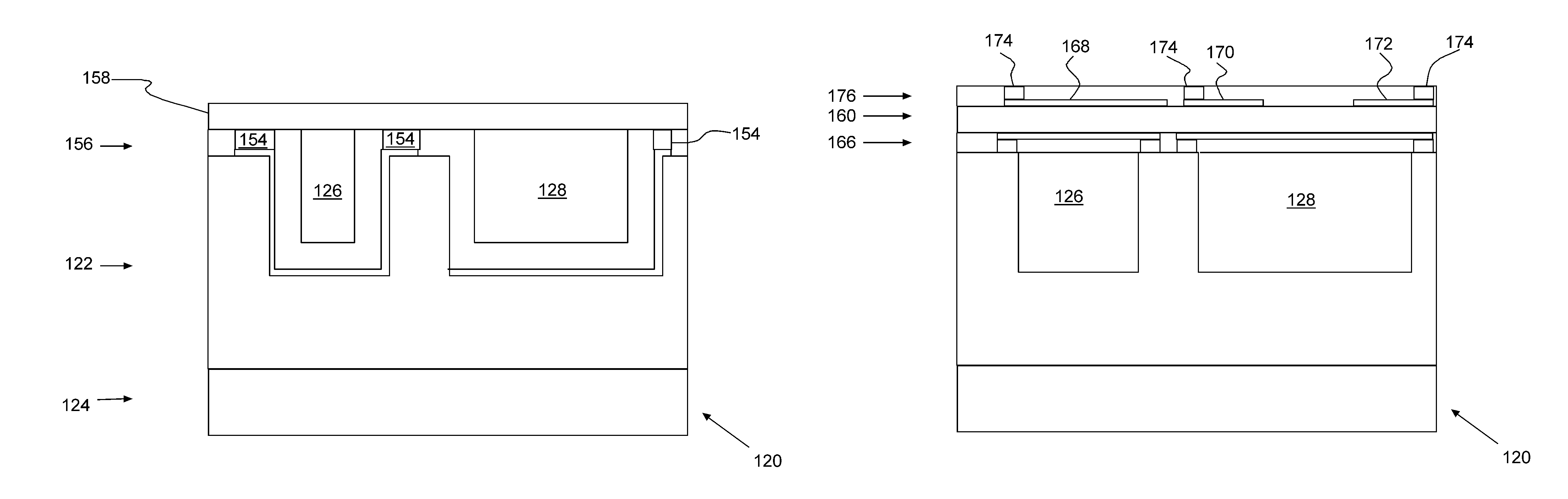
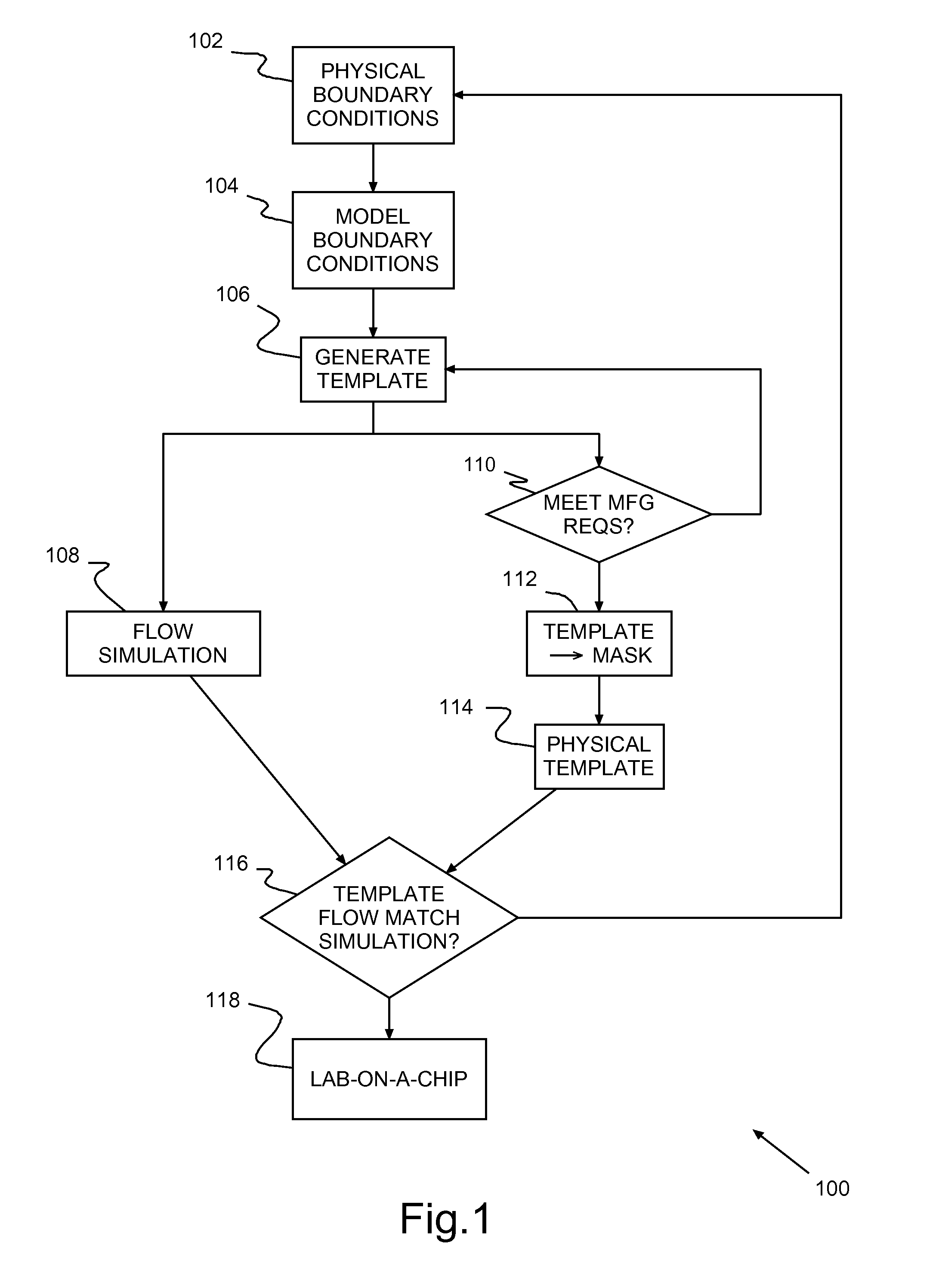
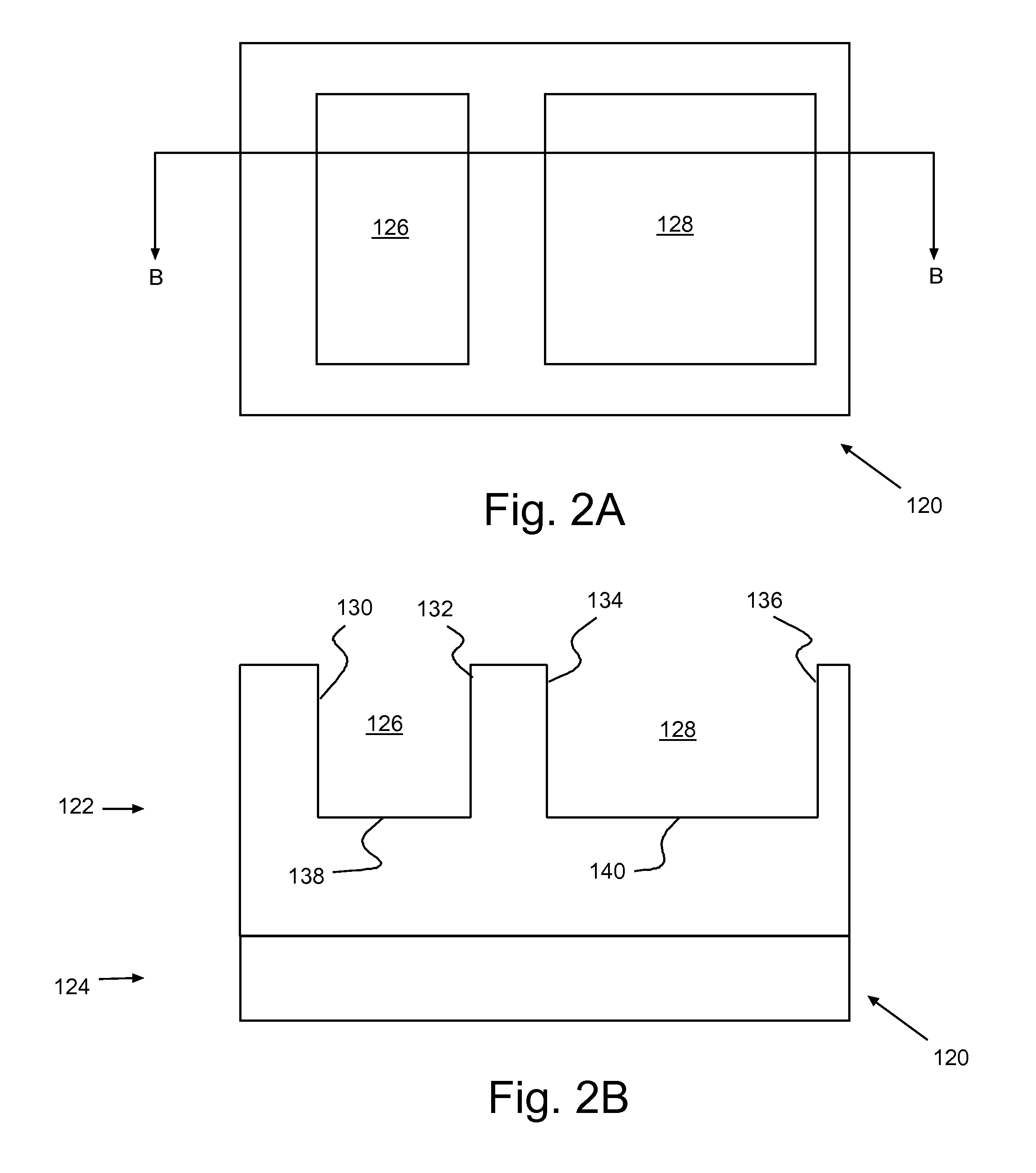
[0019]Turning now to the drawings and, more particularly, FIG. 1 shows an example 100 of fabricating a lab-on-a-chip for simulating fluid flow according to a preferred embodiment of the present invention. Essentially, the lab-on-a-chip fabrication 100 uses typical state of the art semiconductor integrated circuit fabrication techniques (e.g., CMOS chip fabrication) to form a template or templates and sufficient wiring and analysis support circuitry. The template has physical patterns that represent fluid flow in a geological space. Once formed and verified / validated, the template simulates fluid flow through fluid channels representative of the geological space. Typically the fully formed template structure is capped with a capping layer. The capping layer may include the simulation support circuitry, or the simulation support circuitry may be opposite the cap, on or in, the same semiconductor wafer supporting the template(s). Thus, the lab-on-a-chip enables liquid flow analysis thr...


PUM

PropertyMeasurementUnit
widthaaaaaaaaaa
aspect ratiosaaaaaaaaaa
surface-to-aaaaaaaaaa

Abstract

An Integrated Circuit (IC) chip with a lab-on-a-chip, a method of manufacturing the lab-on-a-chip and a method of using the lab-on-a-chip for fluid flow analysis in physical systems through combination with computer modeling. The lab-on-a-chip includes cavities in a channel layer and a capping layer, preferably transparent, covering the cavities. Gates control two dimensional (2D) lattice structures acting as heaters, light sources and / or sensors in the cavities, or fluid channels. The gates and two dimensional (2D) lattice structures may be at the cavity bottoms or on the capping layer. Wiring connects the gates and the 2D lattice structures externally.

Description

BACKGROUND OF THE INVENTION[0001]1. Field of the Invention[0002]The present invention generally relates to analyzing liquid flow and liquid-solid interface interaction and more particularly to an integrated device for self-contained liquid flow and liquid-solid interface interaction analysis that enables the comparison with and the validation of computational models of such liquid solid interactions.[0003]2. Background Description[0004]Hydrocarbon fuels, e.g., oil and natural gas, are valuable commodities. It is important to understand how oil is situated and flowing in an oil field in order to make decisions about, for example, where to drill, how deep to drill, how many wells to drill, as well as how to chemically enhance hydrocarbon recovery in such fields. Thus, major resources may be expended in modeling a field to facilitate making these dimensions. While a typical computer model may be used to simulate the field, the simulations may not allow engineers to sufficiently visuali...

Claims


Application Information

Patent Timeline
Patent Type & Authority Patents(United States)
IPC IPC(8): H01L21/768H01L21/762H01L21/02G06F17/50H01L29/49H01L29/16G01N11/04G01N11/00
CPCG01N11/04G06F17/5009G06F17/5068H01L29/1606H01L29/4966G01N2011/008G01N33/24G06F2111/10G06F30/20G06F30/392G01N21/71G01N2201/08
Inventor AVOURIS, PHAEDONENGEL, MICHAELFEGER, CLAUDIUSGIRO, RONALDOFERREIRA, RODRIGOSTEINER, MATHIAS
Owner INT BUSINESS MASCH CORP
Why Eureka
Try Eureka