Seat sliding device for vehicle

a technology for sliding devices and seats, which is applied in the direction of vehicle components, vehicle supports, vehicle arrangements, etc., can solve the problems of significant decrease in bending strength of the upper rail, and achieve the effect of suppressing the decrease in bending strength of the second rail

Active Publication Date: 2016-04-19
AISIN SEIKI KK
View PDF7 Cites 14 Cited by
  • Summary
  • Abstract
  • Description
  • Claims
  • Application Information

AI Technical Summary

Benefits of technology

[0010]An object of the present invention is to provide a seat sliding device for a vehicle in which, while a lock plate for restricting relative movement between rails is penetrated into one of the rails in the widthwise direction, the rail concerned can be suppressed from a decrease in bending strength.
[0013]According to the respective above-described aspects, when the lever part coupled to the second rail rotationally moves in one direction by the urging force of the urging member and the latching part of the lock plate engages with the latched part of the first rail, restrictions are placed on relative movement between the first rail and the second rail. On the other hand, when the lever part coupled to the second rail rotationally moves in the other direction against the urging force of the urging member and the latching part of the lock plate is released from the latched part of the first rail, the restrictions on the relative movement between the first rail and the second rail are released. In these cases, the side wall part through holes and the folded wall part through holes have a closed shape for avoiding interference with the lock plate. Thereby, it is possible to suppress a decrease in bending strength of the second rail as compared with a case that they have an open (opening) shape, for example, like a conventional example.

Problems solved by technology

In this case, the notches are given as stress concentrating sites on application of bending loads to the upper rail, thus inevitably resulting in a significant decrease in bending strength of the upper rail.

Method used


Image

  • Seat sliding device for vehicle
  • Seat sliding device for vehicle
  • Seat sliding device for vehicle

Examples


Embodiment Construction

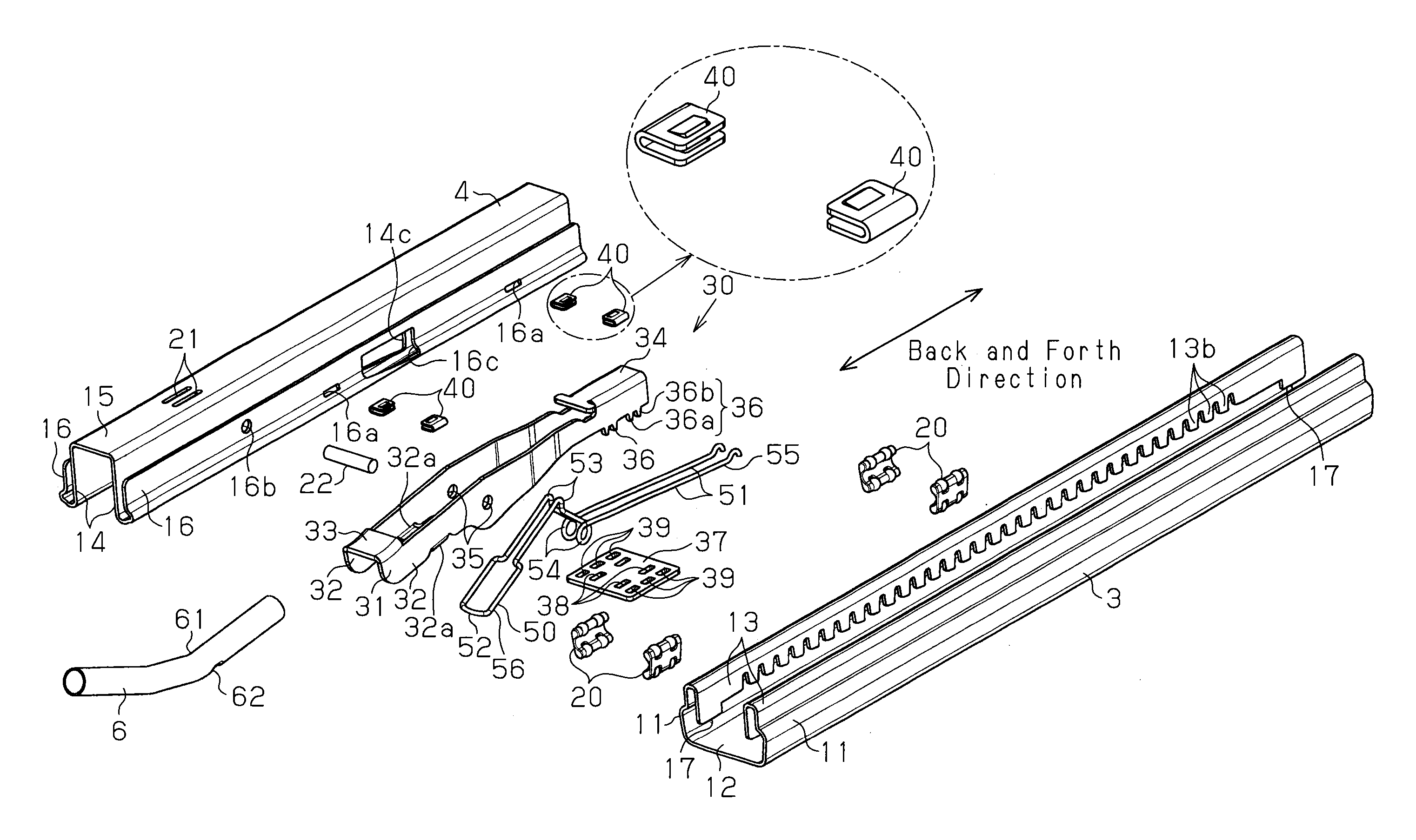
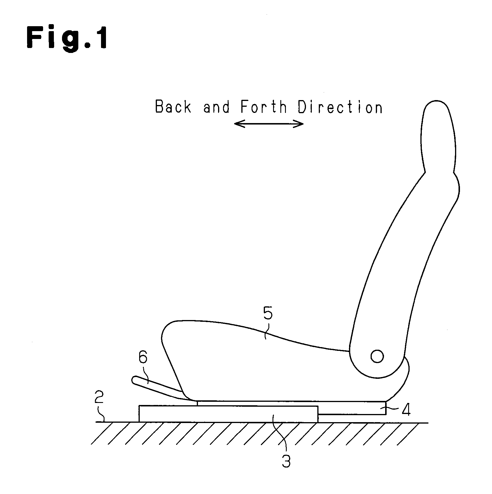
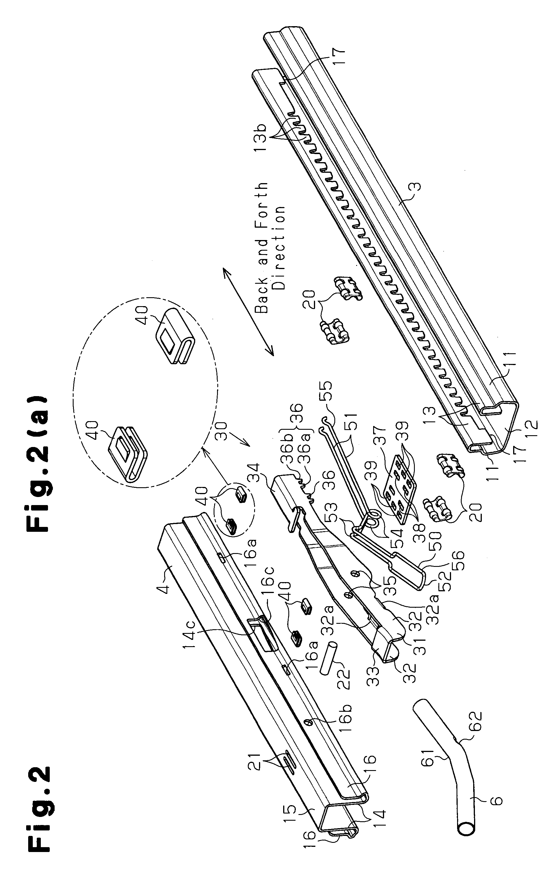
[0025]A description will be given of one embodiment of the present invention with reference to FIG. 1 to FIG. 5. As shown in FIG. 1, a lower rail 3 as a first rail is fixed on a vehicle floor 2 in such a manner to extend in the back and forth direction of a vehicle. An upper rail 4 as a second rail is attached to the lower rail 3 to make relative movement with respect to the lower rail 3 in the back and forth direction.

[0026]A pair of the lower rail 3 and the upper rail 4 shown in FIG. 1 is one of two pairs placed in the widthwise direction of the vehicle (a direction orthogonal to the space in FIG. 1), with an interval therebetween. In this case, there is shown the pair arranged on the left side with respect to the front. A seat 5 on which a passenger sits is fixed and supported on the upper rails 4. Normally, relative movement of the upper rail 4 with respect to the lower rail 3 is kept restricted in principle. There is arranged a release handle 6 which releases the restricted sta...


PUM


Abstract

A seat sliding device for a vehicle includes a first rail and a second rail coupled to the first rail to make relative movement with respect to the first rail. A lever is coupled to the second rail to rotate about an axis extending in the widthwise direction, and a lock plate which is fixed to the rear end part of the lever part and arranged between first side wall parts to extend in the widthwise direction astride side wall part through holes and folded wall part through holes. At both edge parts of the lock plate in the widthwise direction, there is formed a latching part which engages with a latched part of the first rail when the lever part rotationally moves in one direction and is released from the latched part when the lever part rotationally moves in the other direction.

Description

FIELD OF THE INVENTION[0001]The present invention relates to a seat sliding device for a vehicle, which is to adjust the relative position between a vehicle floor and a seat.BACKGROUND OF THE INVENTION[0002]There have been so far proposed various types of a seat sliding device for a vehicle. For example, a seat sliding device for a vehicle disclosed in Patent Document 1 is provided with a lower rail which has an opening that is opened upward, the cross section of which is substantially U-shaped, and an upper rail which blocks the opening, the cross section of which is substantially U-shaped. The lower rail engages with the upper rail to slide with each other in a longitudinal direction. And, a lock lever is supported on the upper rail.[0003]That is, the lock lever is provided with a rivet arranged inside a U-shaped cross section of an attachment part of the lock lever and a spring pin, which penetrates through the attachment part, and also the rivet in a widthwise direction. The riv...

Claims


Application Information

Patent Timeline
Patent Type & Authority Patents(United States)
IPC IPC(8): F16M13/00B60N2/08B60N2/07
CPCB60N2/07B60N2/0705B60N2/0715B60N2/08B60N2/085B60N2/0818B60N2/0887
Inventor YAMADA, YUKIFUMIGOTO, NAOKI
Owner AISIN SEIKI KK
Why Eureka
Try Eureka