Pocketed concrete anchor

a concrete anchor and pocket technology, applied in the field of systems, can solve the problems of loss of performance of concrete anchors, and achieve the effects of reducing the weight of each concrete anchor, reducing the use of raw materials, and creating production savings

Active Publication Date: 2016-04-19
PRECISION HAYES INT INC
View PDF24 Cites 12 Cited by
  • Summary
  • Abstract
  • Description
  • Claims
  • Application Information

AI Technical Summary

Benefits of technology

[0013]One advantage of the present invention is that it provides for a reduction in total raw materials necessary to form the anchor, and thus, creates savings in production of the pocketed concrete anchor. As a result of the reduced raw material used in producing the pocketed concrete anchor, the weight of each concrete anchor is reduced, which in turn results in savings in shipping costs. Importantly, these advantages are not gained at the expense of a loss in performance of the concrete anchor.
[0014]In fact, performance of the anchor is improved in that another advantage of the present invention is that the pocket in the anchor's flange provides for an increased surface area of the anchor. The increased surface area of the present invention provides more gripping surface for anchors that are encapsulated in the concrete after tensioning by the hydraulic jack tensioners. This results in a more robust anchor as part of a post-tensioned concrete reinforcement system.

Problems solved by technology

Importantly, these advantages are not gained at the expense of a loss in performance of the concrete anchor.

Method used


Image

  • Pocketed concrete anchor
  • Pocketed concrete anchor
  • Pocketed concrete anchor

Examples


Embodiment Construction

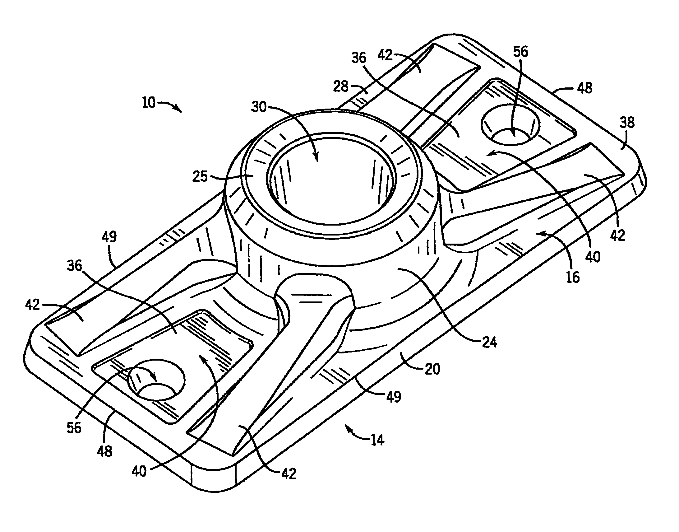
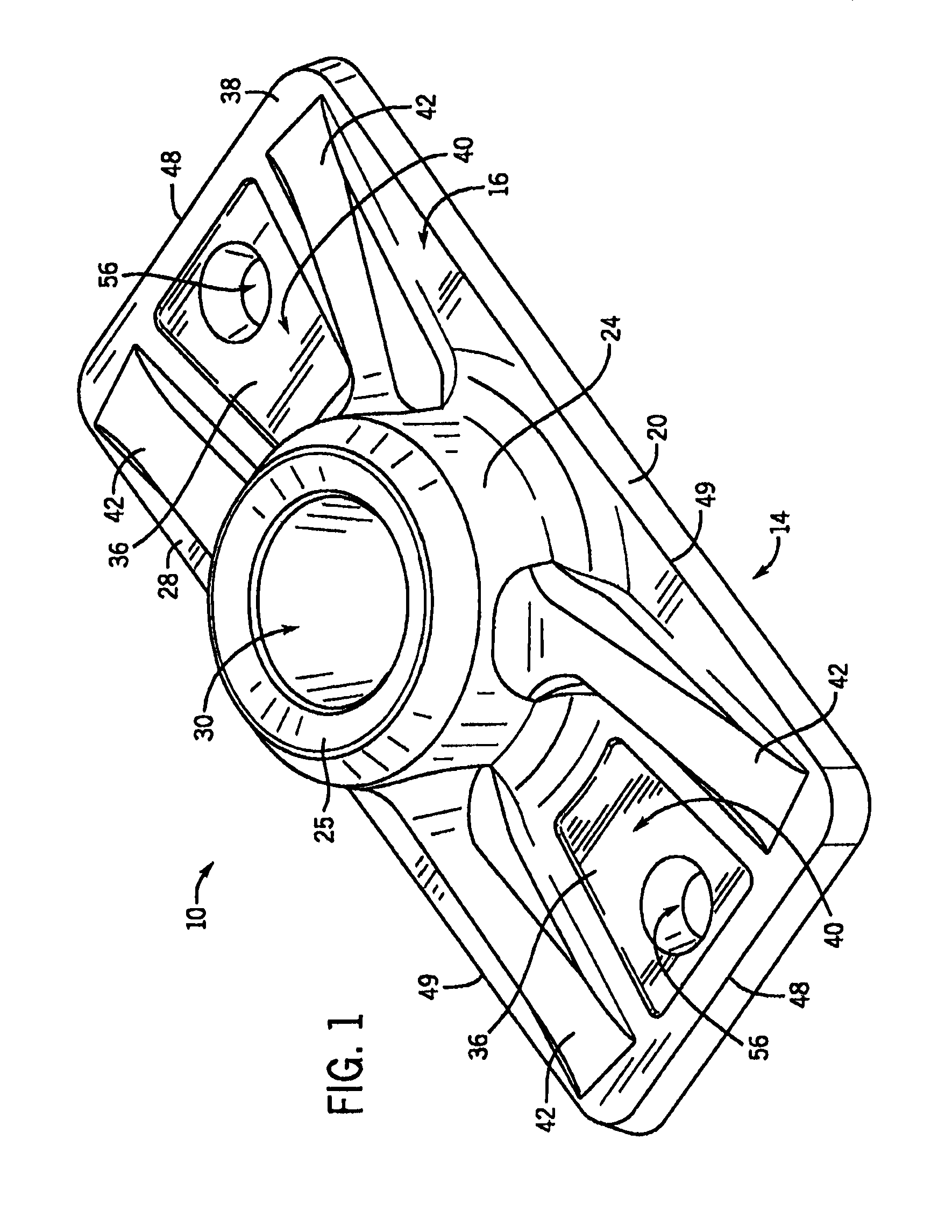
[0019]Referring to FIG. 1, a pocketed concrete anchor 10 embodying the present invention is illustrated. The pocketed concrete anchor 10 has a body with a flange portion 14 that has both a front and rear surface 16, 18, as well as an edge surface 20. The body also includes a button portion 22, as seen in FIGS. 3 and 4, that extends from the rear surface 18 of the flange 14 and a nose portion 24 that extends from the front surface 16 of the flange 14. The nose portion 24 may be structured such that it has a seating surface 25 that can engage a hydraulic jack tensioner (not shown) during the tensioning of the tendon 34.

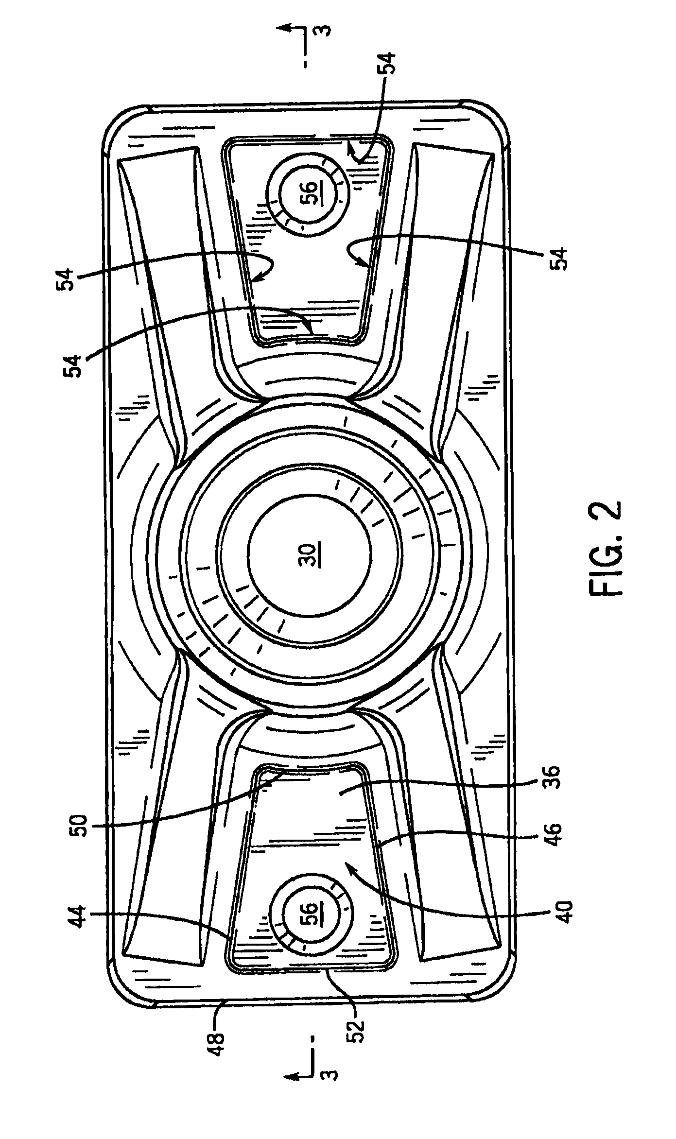
[0020]As seen in FIG. 1, the flange 14 may be rectangular in shape and the nose and button portions 24, 22 may be centered on the flange 14. The flange 14 extends laterally from both the nose portion 24 and the button portion 22 to opposite distal edges 48 on the lateral sides of the nose and button portions 24, 22 and to opposite proximal edges 49 on the transverse sid...


PUM


Abstract

The invention provides for a pocketed anchor for post-tensioned concrete reinforcement. The anchor includes a body having a flange portion with a front and rear surface, a button portion extending from the rear surface, and a nose portion extending from the front surface. The anchor also includes a tapered bore that extends through the nose, flange, and button portions. The bore can receive a wedge that cams against the bore to clamp down on a tendon. The front surface of the flange has at least two planar surfaces that are parallel to the bearing surface on the rear surface of the anchor. One of the planar surfaces is recessed relative to the other such that the recessed surface is closer to the load bearing surface on the rear surface of the anchor. The two planar surfaces define a pocket on the anchor, where mounting holes may be located.

Description

CROSS REFERENCE TO RELATED APPLICATIONS[0001]This application claims the benefit of U.S. Provisional Patent Application No. 61 / 363,889 filed Jul. 13, 2010, which is hereby incorporated by reference.STATEMENT OF FEDERALLY SPONSORED RESEARCH OR DEVELOPMENT[0002]Not applicable.FIELD OF THE INVENTION[0003]The present invention relates to a system for providing concrete with post-tensioned reinforcement. More specifically, the invention relates to an anchoring structure used in a post-tensioned reinforcement system.BACKGROUND OF THE INVENTION[0004]Concrete is capable of withstanding significant compressive loads, however, it is not as capable of withstanding significant tensile loads. Thus, it is often necessary to reinforce concrete structures with steel bars, cables, or the like to enhance the structure's ability to withstand tensile forces.[0005]The basic principles of providing such reinforcement to concrete structures are known in the prior art. In a post-tensioned reinforcement sys...

Claims


Application Information

Patent Timeline
Patent Type & Authority Patents(United States)
IPC IPC(8): E04C5/12G06F3/0484A61B5/00A61B5/044A61B19/00G06F9/46G16H10/60
CPCG06F3/04842E04C5/122E04C5/12
Inventor STANFORD, FRANTZ
Owner PRECISION HAYES INT INC
Why Eureka
Try Eureka