
Analyzer, and method for performing a measurement on a sample

a technology of analyzer and sample, which is applied in the field of clinical analyzers, can solve the problems of difficult to ensure that such an operator is actually operating the analyzer, and the operator may not follow the various procedures required for accurate testing of patient blood samples

Active Publication Date: 2016-04-19
SYSMEX CORP
View PDF79 Cites 3 Cited by
  • Summary
  • Abstract
  • Description
  • Claims
  • Application Information

AI Technical Summary

Benefits of technology

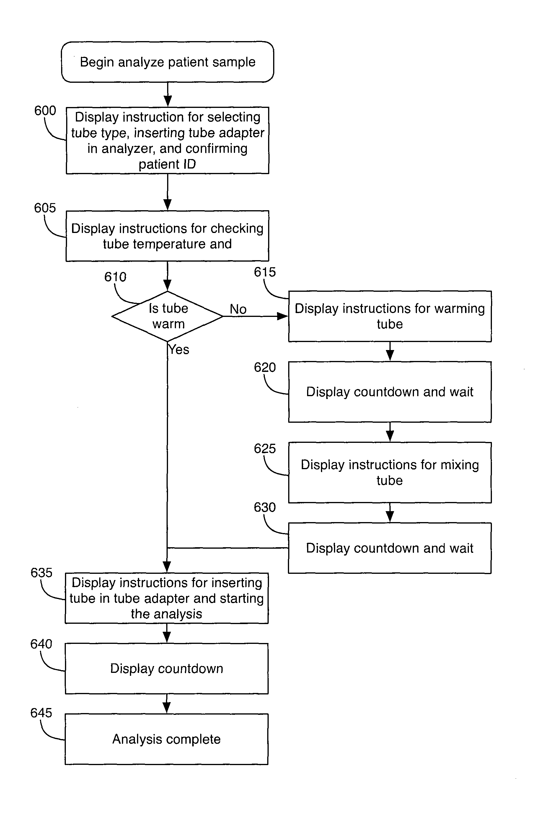
This patent describes an analyzer that can perform different procedures on a sample to prepare it for measurement. The analyzer has a display and measurement hardware, and a controller that can communicate with the display to perform the procedures. The controller can also maintain the analyzer in a state associated with a first procedure for a specific amount of time. After the time has passed, the controller can communicate with the display to perform a second procedure on the sample. The technical effect of this invention is to provide a flexible and efficient way to prepare samples for measurement, with the ability to perform different procedures sequentially or simultaneously.

Problems solved by technology

Many known hematology analyzers are large cumbersome machines placed in hospitals and laboratories.
However, it is difficult to guarantee that such an operator is actually operating the analyzer.
Even when trained, the operator may not follow the various procedures required for accurate testing of a patient blood sample.
When the operator skips this step, the samples may become unusable for future quality control checks as the consistency of the samples may change.
Thus, a new sample may be required, which will necessarily increase the cost associated with operation of the analyzer.
When an operator fails to perform this procedure correctly, the measurement may fail or give inaccurate results.
Other problems with known analyzers will become apparent upon reading the descriptions of the various embodiments described below.

Method used


Image

  • Analyzer, and method for performing a measurement on a sample
  • Analyzer, and method for performing a measurement on a sample
  • Analyzer, and method for performing a measurement on a sample

Examples


Embodiment Construction

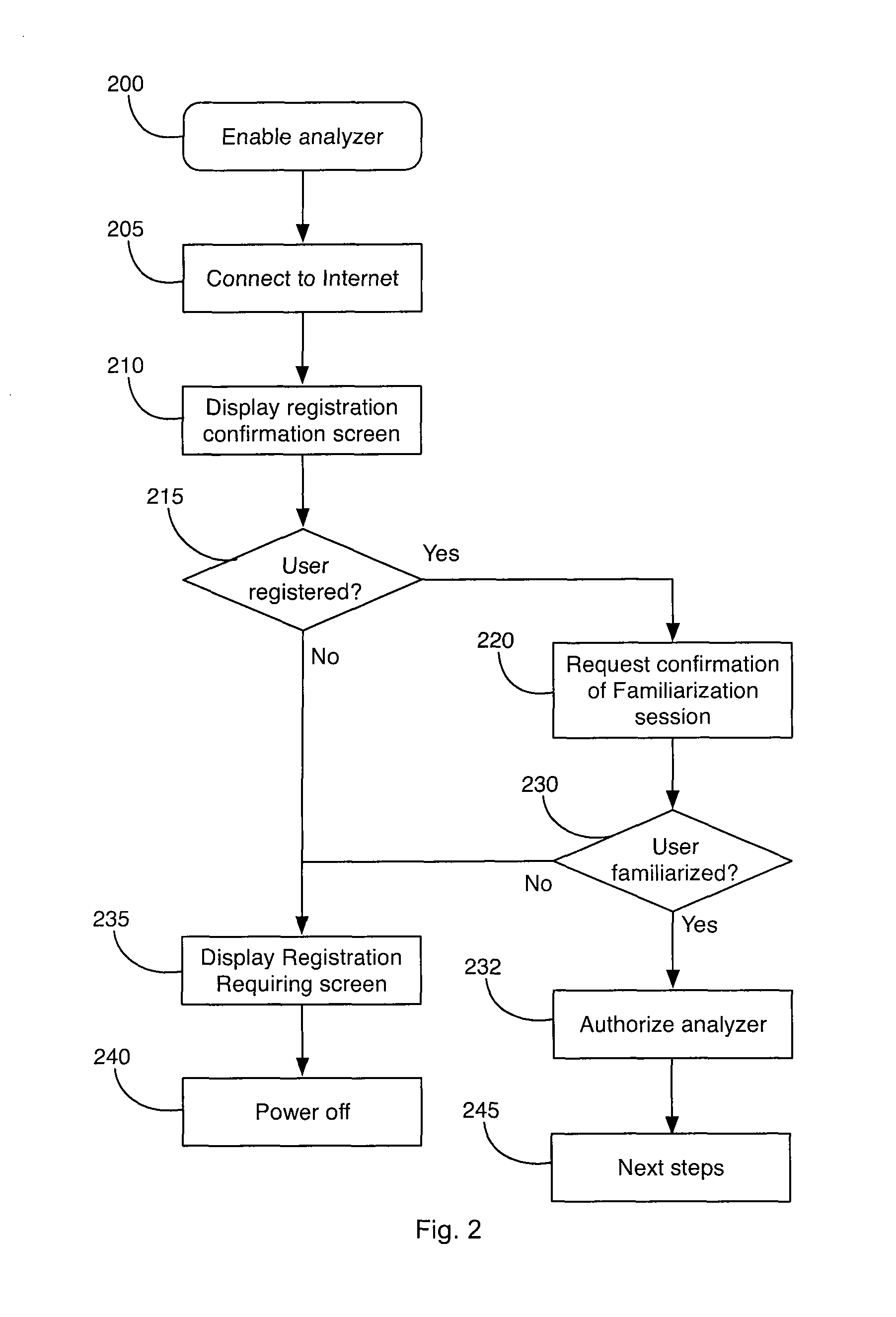
[0021]The embodiments below describe an exemplary embodiment of an analyzer system. For example, the analyzer system may include a hematology analyzer configured to analyze a patient blood sample and a server in communication with the hematology analyzer. In particular, the system is configured to ensure that an operator is qualified to use the analyzer and that the operator adheres to certain procedures while operating the analyzer. In one embodiment, the analyzer system prevents an operator from using an analyzer until it can be confirmed that the operator is qualified to use the analyzer. In second and third embodiments, the operator is presented with step-by-step instructions that guide the operator in the proper use of the analyzer.

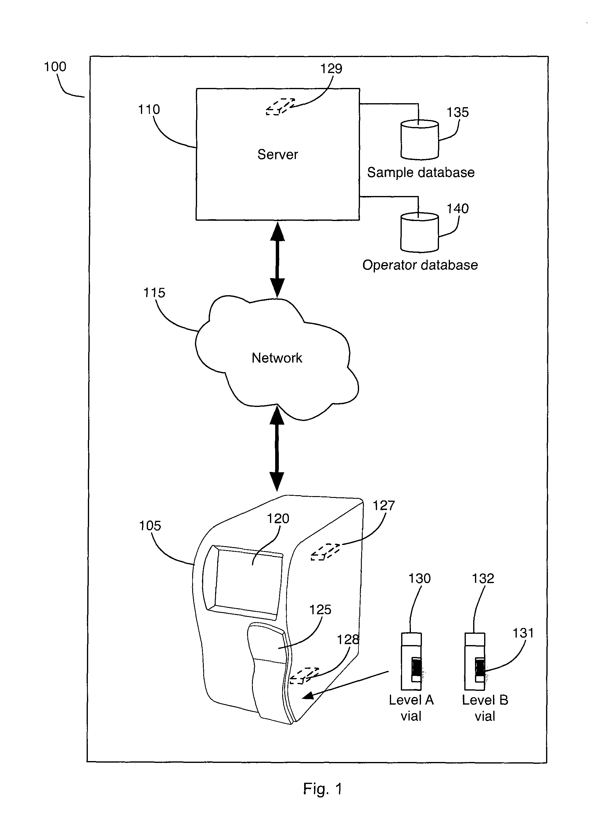
[0022]FIG. 1 is an exemplary hematology analyzer system 100 (hereinafter system). The system 100 includes a hematology analyzer 105 (hereinafter analyzer) and a server 110. The analyzer 105 may include the features of the analyzer of U.S. Pat. No. 6,...


PUM

PropertyMeasurementUnit
timeaaaaaaaaaa
timeaaaaaaaaaa
timeaaaaaaaaaa

Abstract

An analyzer includes a display, measurement hardware configured to perform a measurement on a sample, and a controller. The controller is in communication with the display and the measurement hardware and is configured to communicate, via the display, a first pre-analytical procedure of the sample prior to measurement of the sample. The controller is also configured to maintain the analyzer in a state associated with the first procedure for an amount of time equal to a time needed for performing the first procedure. After the time needed for performing the first procedure has elapsed, the controller is configured to communicate, via the display, a second pre-analytical procedure of the sample prior to measurement of the sample.

Description

BACKGROUND[0001]i) Field[0002]This application relates to an analyzer and its components. In particular, this application relates to a clinical analyzer and system configured to ensure that an operator is qualified to use the analyzer and that the operator adheres to certain procedures while operating the analyzer.[0003]ii) Description of the Related Art[0004]Hematology analyzers are utilized to make various measurements of the constituents of a blood sample. Many known hematology analyzers are large cumbersome machines placed in hospitals and laboratories. Such analyzers are required to be operated by an operator officially certified to operate the analyzers.[0005]Smaller hematology analyzers, such as the analyzers described in U.S. Pat. Nos. 6,772,650 and 7,013,260, are designed to be placed in a doctor's office where space is at a premium. Like the analyzers described above, a certified operator may operate these machines.[0006]However, it is difficult to guarantee that such an o...

Claims


Application Information

Patent Timeline
Patent Type & Authority Patents(United States)
IPC IPC(8): G01N33/48G06F19/20G01N35/00
CPCG01N35/00623G06F19/20G16B25/00G01N33/48
Inventor AUSDENMOORE, JAMESOSELLA, PETERTAYLOR, RALPH
Owner SYSMEX CORP
Learn More