
Method and apparatus for examining measurement tip of scanning probe microscope

A scanning probe and microscope technology, used in scanning probe microscopy, scanning probe technology, measuring devices, etc. The effect of reducing the outline

Pending Publication Date: 2020-05-15
CARL ZEISS SMT GMBH
View PDF14 Cites 1 Cited by
  • Summary
  • Abstract
  • Description
  • Claims
  • Application Information

AI Technical Summary

Problems solved by technology

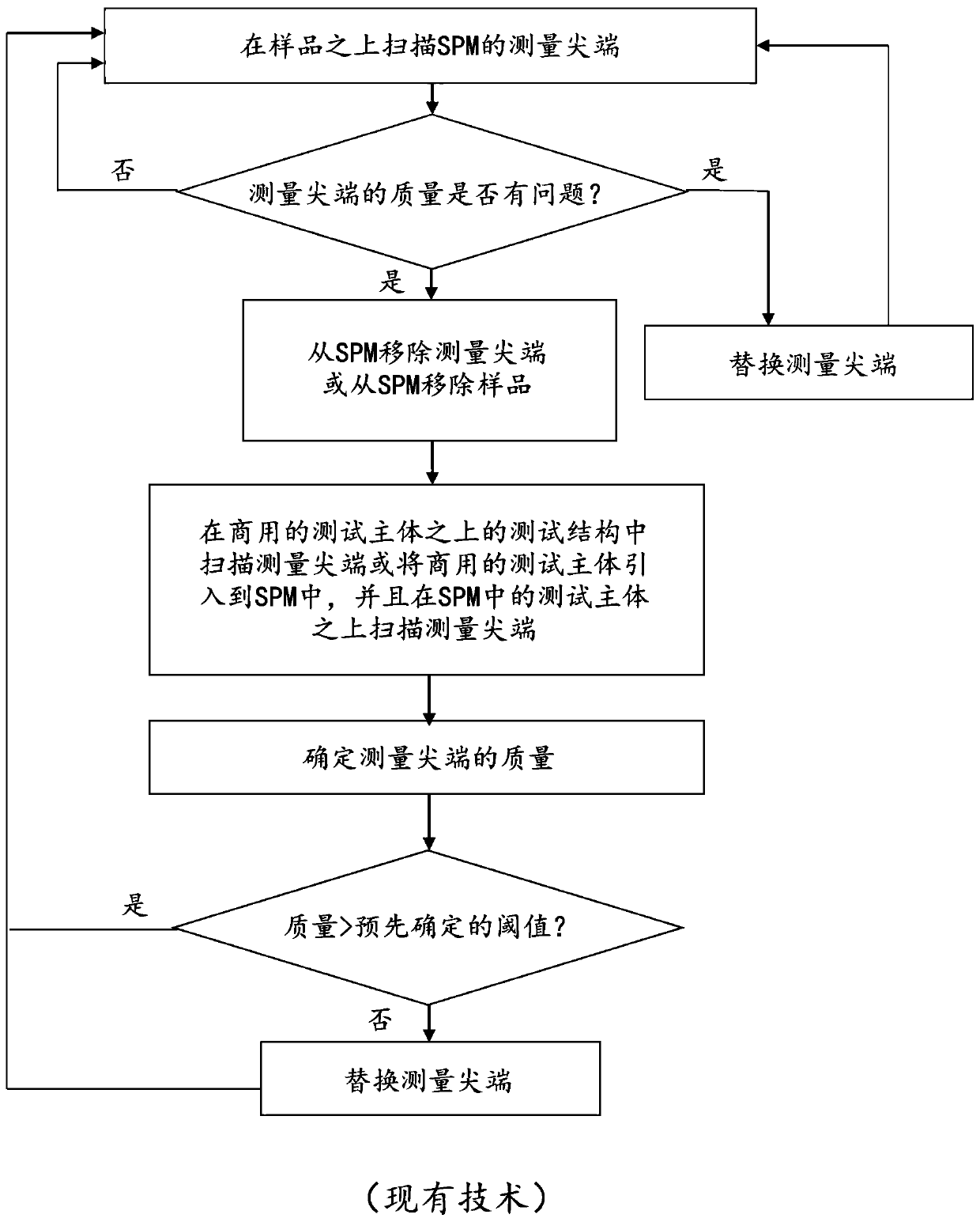
This process firstly leads to the discarding of still usable probes, which will be associated with significant costs, and secondly leads to a longer downtime of the scanning probe microscope due to the frequent replacement of the probes

Method used


Image

  • Method and apparatus for examining measurement tip of scanning probe microscope
  • Method and apparatus for examining measurement tip of scanning probe microscope
  • Method and apparatus for examining measurement tip of scanning probe microscope

Examples


Embodiment Construction

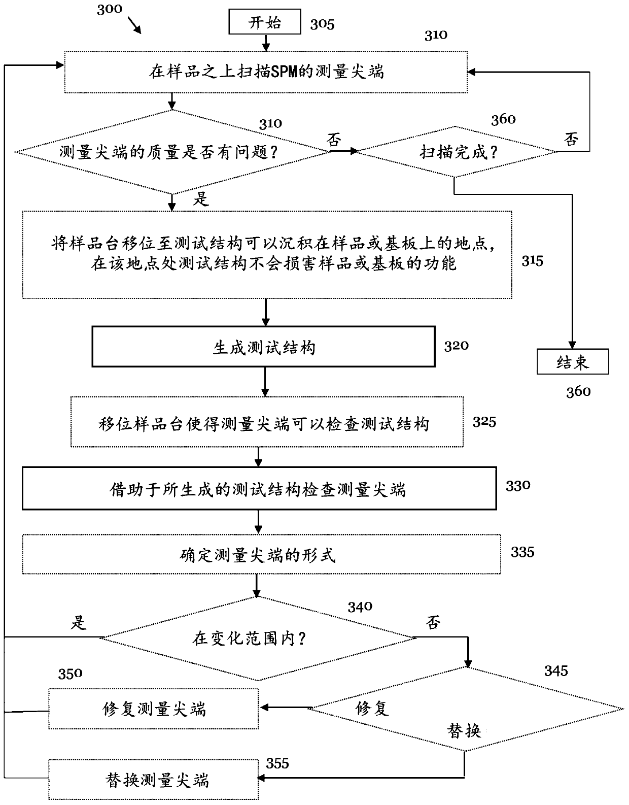
[0107] In the following, a presently preferred embodiment of a method for inspecting a measuring tip of a scanning probe microscope (SPM) according to the present invention is explained in more detail, taking an atomic force microscope (AFM) as an example. However, the method according to the invention is not limited to the application of atomic force microscopy. On the contrary, the method according to the invention can be used in all types of scanning probe microscopes, the measuring tip of which is subject to wear due to the interaction with the sample. Additionally, the defined method can be used to check for dirty measuring tips due to scanning the measuring tip over the sample surface.

[0108] In the following, the method according to the invention is explained using the example of analysis of a photolithography mask with a measuring tip of an AFM. However, the application of the method according to the invention is not limited to scanning on photolithographic masks. ...


PUM


Abstract

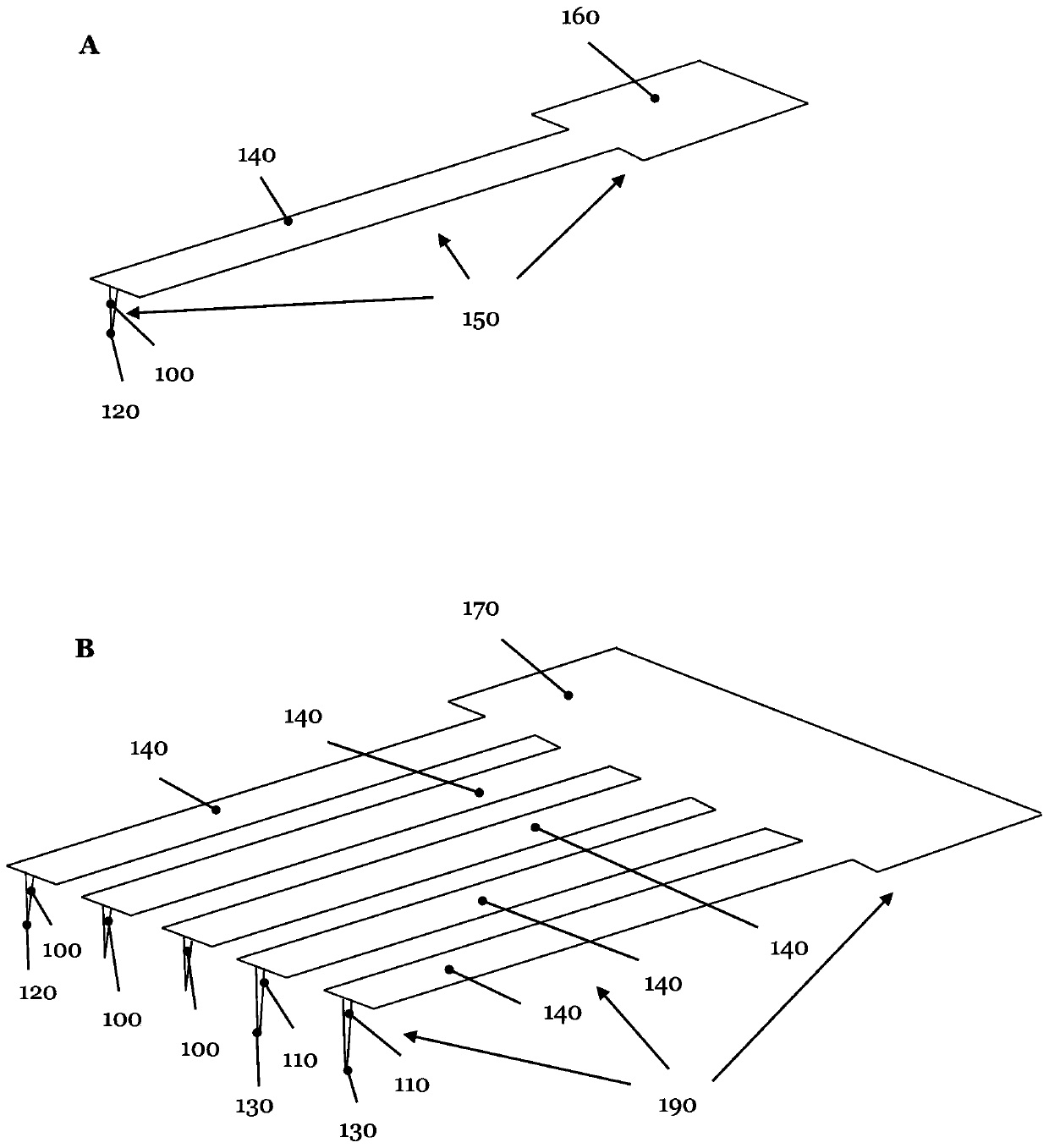
The present invention relates to a method for examining a measurement tip (100, 110) of a scanning probe microscope (520), wherein the method includes the following steps of (a) producing at least onetest structure (600, 650, 710, 730, 750, 770, 810, 850) before or after analyzing a sample (400, 510) by means of the measuring tip (100, 110); and (b) examining the measuring tip (100, 110) with theaid of the at least one test structure (600, 650, 710, 730, 750, 770, 810, 850) produced.

Description

[0001] This patent application claims priority from German patent application DE10 2017211 957.8 filed at the German Patent and Trademark Office on July 12, 2017, the entire content of which is hereby incorporated by reference. [0002] 1. Technical field [0003] The invention relates to a method and a device for inspecting a measuring tip of a scanning probe microscope. [0004] 2. Background technology [0005] Scanning probe microscopes use a measurement tip to sense a sample or its surface, and thus generate measurement data to produce a representation of the topography of the sample surface. In the following, the scanning probe microscope is abbreviated as SPM. Depending on the type of interaction between the measuring tip and the sample surface, a distinction is made between various SPM types. Typically a scanning tunneling microscope (STM) is used, where a voltage is applied between the sample and the measuring tip, which do not come into contact with each other, and ...

Claims


Application Information

Patent Timeline
IPC IPC(8): G01Q40/00G01Q40/02
CPCG01Q30/02G01Q40/00G01Q40/02G01Q20/02G01Q70/06G01Q70/08
Inventor K.科尼洛夫C.鲍尔M.鲍尔
Owner CARL ZEISS SMT GMBH
Learn More