Capacitive transducer

a capacitive transducer and acoustic sensor technology, applied in the direction of solid-state device transducers, electrostatic transducers of semiconductor electrostatic transducers, loudspeakers, etc., can solve the problems of no longer detecting acoustic vibration, no longer able to detect acoustic vibration by acoustic sensors, and a large amount of stress, so as to improve the anti-sticking property and improve the anti-breaking property

Active Publication Date: 2016-04-19
MMI SEMICON CO LTD
View PDF9 Cites 11 Cited by
  • Summary
  • Abstract
  • Description
  • Claims
  • Application Information

AI Technical Summary

Benefits of technology

[0015]One or more embodiments of the present invention provides a capacitive transducer capable of improving both the anti-sticking, and the anti-breaking properties of the diaphragm.
[0017]In the capacitive transducer according to one or more embodiments of the invention, a first stopper of comparatively short protruding length is provided at a position corresponding to a first position where the amount of displacement of the diaphragm is comparatively large; a second stopper of comparatively long protruding length is provided at a position corresponding to a second position where the amount of displacement of the diaphragm is comparatively small. Consequently, a first stopper of comparatively short protruding length is provided at a position corresponding to a first position where the amount of displacement of the diaphragm is comparatively large, and thus, when the diaphragm abuts the first stopper, the diaphragm may undergo a large displacement and acquire a large elastic restorative force. Accordingly, the diaphragm tends not to stick to the stopper. Furthermore, a second stopper of comparatively long protruding length is provided at a position corresponding to a second position where the amount of displacement of the diaphragm is comparatively small, and thus, when a diaphragm is subject to a pressure resulting in a large load at locations of diaphragm that undergo a small displacement (i.e., locations at which stress is likely to be concentrated such as portions near where the diaphragm is fixed), the diaphragm may be configured so that the second stoppers abut these locations, thereby preventing the diaphragm from breaking.
[0026]A capacitive transducer according to one or more embodiments of the invention may be configured such that the second stopper is thicker than the first stopper. While the stress concentrates on the portion of the diaphragm in contact with the second stopper because the second stopper has a longer protruding length, the thicker second stopper increases the contact surface area with the diaphragm, to thus disperse the stress at the contact surface.
[0027]A capacitive transducer according to one or more embodiments of the invention may be provided with a plurality of stoppers including a first stopper and a second stopper; the density of the number of stoppers near the second stopper may be greater than the density of the number of stoppers near the first stopper. While the stress concentrates on the portion of the diaphragm in contact with the second stopper for the second stopper having a long protruding length, the increased density of the second stoppers increases the contact surface area of the second stoppers with the diaphragm to thus disperse the stress of the contact surface.
[0030]According to one or more embodiments of the present invention, the diaphragm tends not to stick to the stopper and has an improved anti-sticking property even when the diaphragm is subject to a large load. Moreover, when the diaphragm is subject to a large load, it is possible to prevent a large amount of stress from concentrating on the diaphragm to thereby improve the anti-breaking property of the capacitive transducer.

Problems solved by technology

This sticking of the diaphragm may be caused when, for example, a large sound wave impinges on the diaphragm; a large amount of compressed air (air pressure) impinges on the diaphragm in an acoustic sensor during a drop test; or air is drawn forcefully into the acoustic sensor.
The sticking may also occur while manufacturing the acoustic sensor.
When the diaphragm sticks to the fixed electrode plate in this manner, this inhibits the vibration of the diaphragm, and thus the acoustic sensor is no longer capable of detecting acoustic vibrations.
As a result, a conventional acoustic sensor is prone to sticking whether the spacing between stoppers is too large or too small, and thus it is necessary to provide stoppers 13 so that a suitable spacing is formed.

Method used


Image

  • Capacitive transducer
  • Capacitive transducer
  • Capacitive transducer

Examples


first embodiment

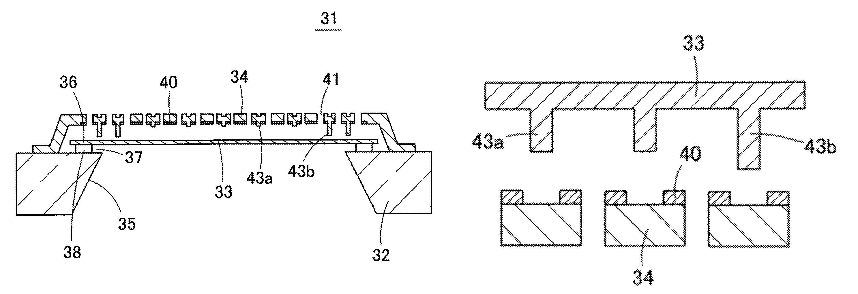
[0060]The structure of an acoustic sensor 31 according to the first embodiment is described with reference to FIG. 3 to FIG. 5. FIG. 3 is a plan view illustrating the acoustic sensor 31 according to the first embodiment. FIG. 4 is a schematic cross-sectional view of the acoustic sensor 31. FIG. 5 is a plan view illustrating the shape of a diaphragm 33 (movable electrode) formed over the upper surface of a substrate 32.

[0061]The acoustic sensor 31 is a capacitive transducer manufactured using MEMS technology. A movable electrode, that is the diaphragm 33 is formed on a substrate 32 such as a silicon substrate in the acoustic sensor 31, as illustrated in FIG. 4; a back plate 34 is provided above the diaphragm 33 with a minute air gap (space) interposed therebetween.

[0062]A cavity 35 is opened in the substrate 32 passing through from the front surface to the underside of the substrate. The cavity 35 may be formed as a back chamber- or a front chamber depending on how the acoustic senso...

second embodiment

[0103]FIG. 17 is a cross-sectional view of an acoustic sensor 71 according to a second embodiment. In the second embodiment, the stoppers 43b are thicker (a larger diameter) than the stoppers 43a. The stress concentrates at the portion of the stoppers 43b in contact with the diaphragm 33. Therefore it is desirable to ensure that the long stoppers 43b have a larger diameter, thereby increasing the contact surface area of the stoppers 43b and dispersing the stress at the contact surface.

third embodiment

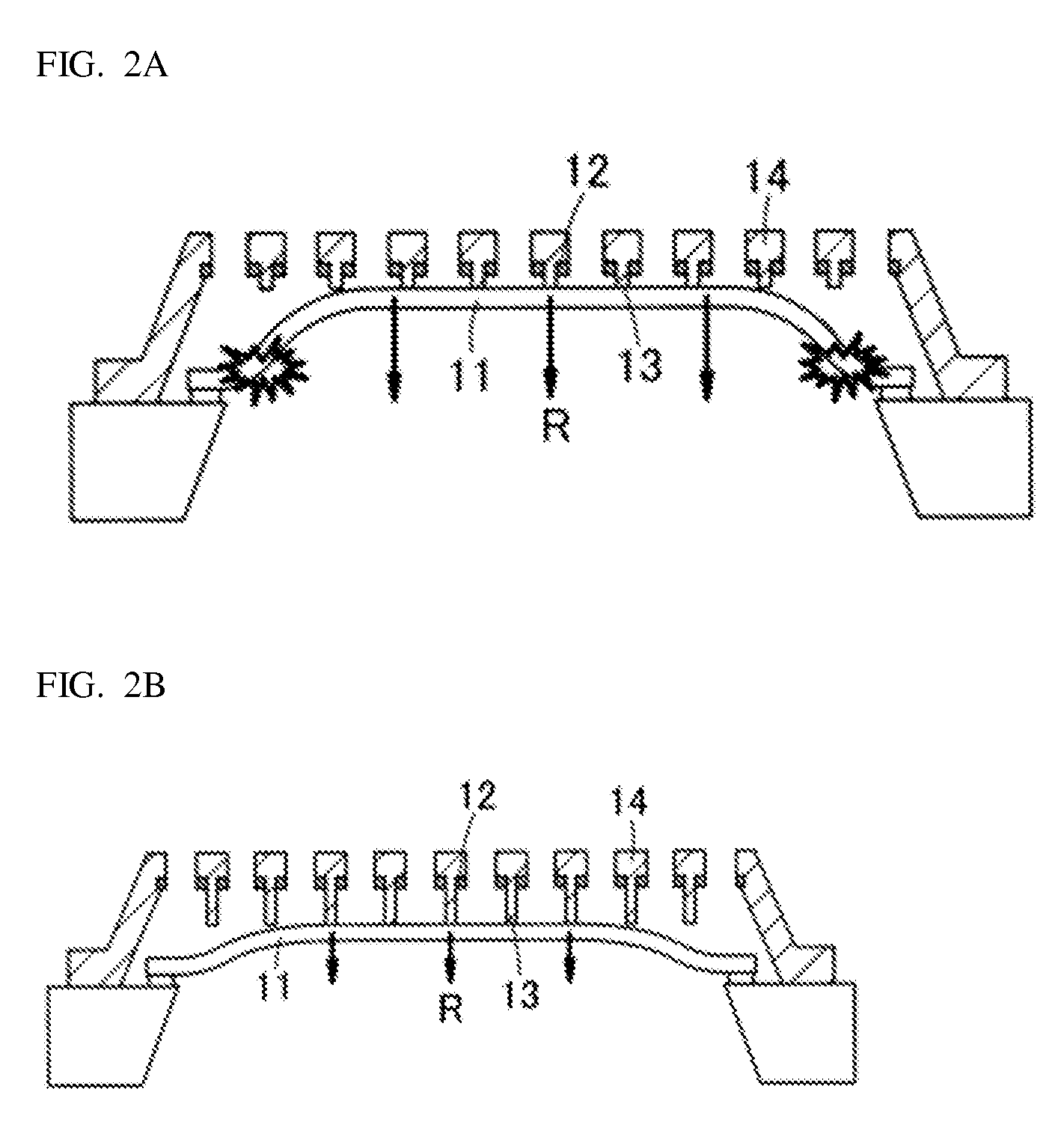
[0104]FIG. 18 is a cross-sectional view of an acoustic sensor 81 according to the third embodiment. In the third embodiment, the short stoppers 43a are provided in a region opposite the center portion of the diaphragm 33, long stoppers 43b are provided at a location opposite the outer peripheral region of the diaphragm; and stoppers 43c longer than the stoppers 43a but shorter than the stoppers 43b are provided in the annular region sandwiched between the central portion and the outer peripheral region on the diaphragm. Increasing the variations to three types of protruding lengths increases the locations of contact when the diaphragm 33 undergoes significant deformation; the increased locations of contact also disperse the stress that concentrates on the stoppers 43a, 43b, 43c, and the anchor 38 to thereby prevent breakage at the stoppers 43a, 43b, 43c, or the diaphragm 33 or the anchor 38, and the like.

[0105]FIG. 19A to FIG. 19C illustrate a portion of manufacturing processes used...


PUM


Abstract

A capacitive transducer has a back plate including a fixed electrode, a diaphragm facing the back plate with an air gap interposed therebetween, the diaphragm acting as a movable electrode, at least a first stopper of a first protruding length, and a second stopper of a second protruding length. The first and second stoppers protrude from at least either the surface on the back plate near the air gap or the surface on the diaphragm near the air gap. The first stopper is provided at a position corresponding to a first position on the diaphragm. The second the stopper is provided at a position corresponding to a second position on the diaphragm. An amount of displacement of the diaphragm at the first position is greater than an amount of displacement of the diaphragm at the second position. The protruding length of the first stopper is shorter than the protruding length of the second stopper.

Description

BACKGROUND[0001]1. Field[0002]The present invention relates to a capacitive transducer, and more specifically relates to a capacitive acoustic sensor.[0003]2. Related Art[0004]One type of capacitive transducer is an acoustic sensor that may be used in a microphone. The acoustic sensor is constructed from a diaphragm (an oscillating electrode plate), and a fixed electrode plate arranged opposite each other with a tiny gap (space) interposed therebetween. The diaphragm is formed from a thin-film about 1 μm thick; therefore, the diaphragm will make minute oscillations in response to the acoustic pressure impinging thereon. Acoustic vibrations may be detected by detecting the change in capacitance when the diaphragm vibrates because the oscillation of the oscillating electrode plate changes the size of the gap between the oscillating electrode plate and the opposing electrode.[0005]For an acoustic sensor constructed in this manner, when the diaphragm 11 flexes greatly and comes in conta...

Claims


Application Information

Patent Timeline
Patent Type & Authority Patents(United States)
IPC IPC(8): H04R25/00H04R19/01H04R19/00H04R23/00H04R31/00H04R19/04
CPCH04R19/005H04R19/016H04R19/04H04R23/006H04R31/00H04R2201/003H01L2224/48091H01L2224/48137H01L2924/15151H01L2924/16152B81B3/001B81B2201/0257H01L2924/00014
Inventor OKUGAWA, AKIHIRO
Owner MMI SEMICON CO LTD
Why Eureka
Try Eureka