Eyeground imaging apparatus and control method therefor

a technology of eyeground imaging and control method, which is applied in the field of eyeground imaging apparatus, can solve the problems of reducing usability and subject whose eyeground is to be imaged has a heavy time load, and achieves the effects of reducing the time load on the subject, facilitating image capture, and efficient captur

Active Publication Date: 2016-05-03
CANON KK
View PDF19 Cites 1 Cited by
  • Summary
  • Abstract
  • Description
  • Claims
  • Application Information

AI Technical Summary

Benefits of technology

[0016]According to the present invention, a surface image of the eyeground can be captured after a tomographic image is checked. Hence, even if there is a need to capture a tomographic image again because of image displacement due to, for example, involuntary eye movement, the tomographic image can be efficiently captured by checking the previous tomographic image. Moreover, the user can more easily capture the image, and the time load on the subject is reduced.

Problems solved by technology

For the above-described reason, the user of the apparatus needs to wait for a long period to capture a tomographic image again after a surface image of the eyeground is captured, and this reduces usability.
Moreover, the subject whose eyeground is to be imaged has a heavy time load.

Method used


Image

  • Eyeground imaging apparatus and control method therefor
  • Eyeground imaging apparatus and control method therefor
  • Eyeground imaging apparatus and control method therefor

Examples


examples _ first example

Examples_First Example: Eyeground Imaging Apparatus and Control Method therefor

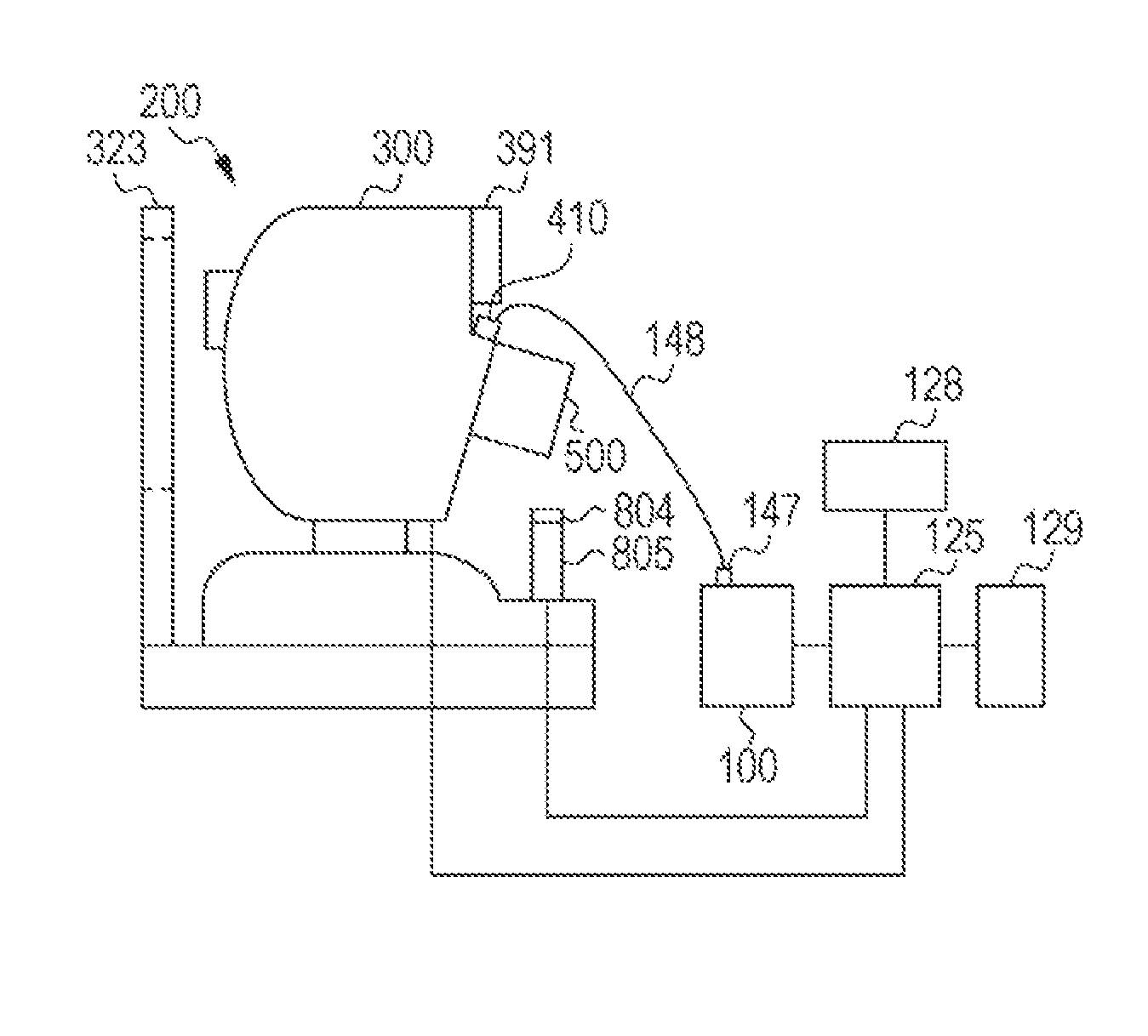
[0058]First, an overall configuration of an eyeground imaging apparatus according to a first example will be described with reference to FIG. 1A. FIG. 1A is aside view of an eyeground imaging apparatus 200 of the first example. The eyeground imaging apparatus 200 includes a tomographic-image pickup unit 100, a retinal-camera main unit 300, and a camera unit 500. The main unit 300 is optically connected to the camera unit 500, and is also optically connected to the tomographic-image pickup unit 100 by an optical fiber 148, The main unit 300 and the tomographic-image pickup unit 100 have a connector 410 and a connector 147, respectively. A jaw rest 323 fixes the jaw and forehead of the subject so as to fix the eye to be examined. A monitor 391 displays, for example, an infrared image for adjustment during image pickup operation.

[0059]A joystick 805 controls movement for aligning the main unit 300 with the e...

examples _ second example

Examples_Second Example: Preview of Tomographic Image

[0092]Next, an eyeground imaging apparatus according to a second example will be described. The second example is different from the first example in a part of a method for capturing a tomographic image and an eyeground image. Since the configuration of the apparatus, configuration of an optical system of the apparatus, and a configuration of a tomographic-image pickup unit are similar to those adopted in the first example, descriptions thereof are omitted, and a method for capturing a tomographic image and an eyeground image will be described.

Method for Capturing Tomographic Image and Eyeground Image 2

[0093]An image capturing method using the eyeground imaging apparatus of the second example will be described with reference to FIGS. 4C and 6, The same structures of the apparatus as those of the first example are denoted by the same reference numerals, Steps in an imaging flowchart shown in FIG. 6 will be described in order.

[0094]...

examples _ third example

Examples_Third Example: Adaptor

[0107]Next, an eyeground imaging apparatus according to a third example will be described.

[0108]The third example is different from the first example in a part of a configuration of the apparatus. In the following, structures similar to those adopted in the first example denoted the same reference numerals, and descriptions thereof are omitted.

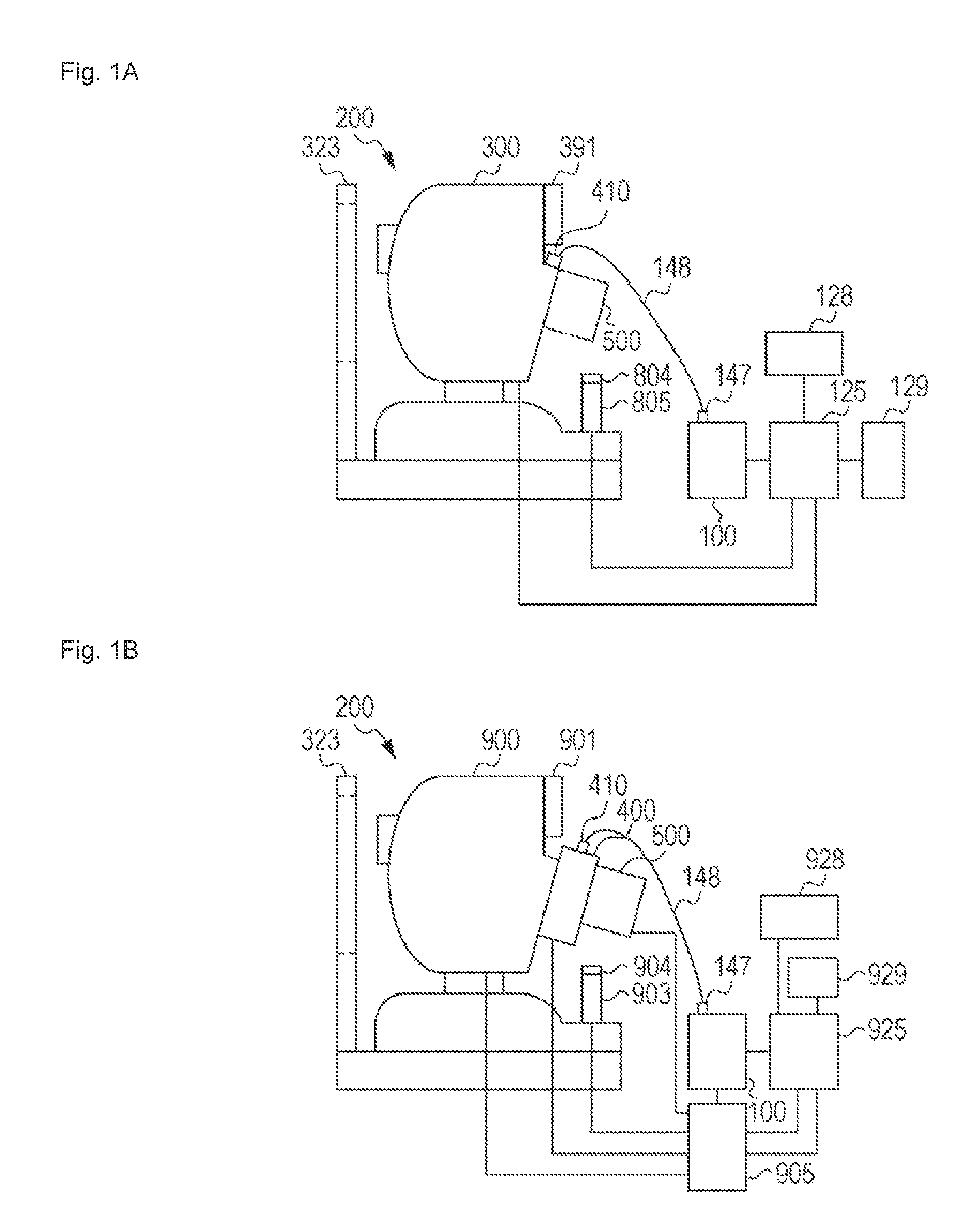
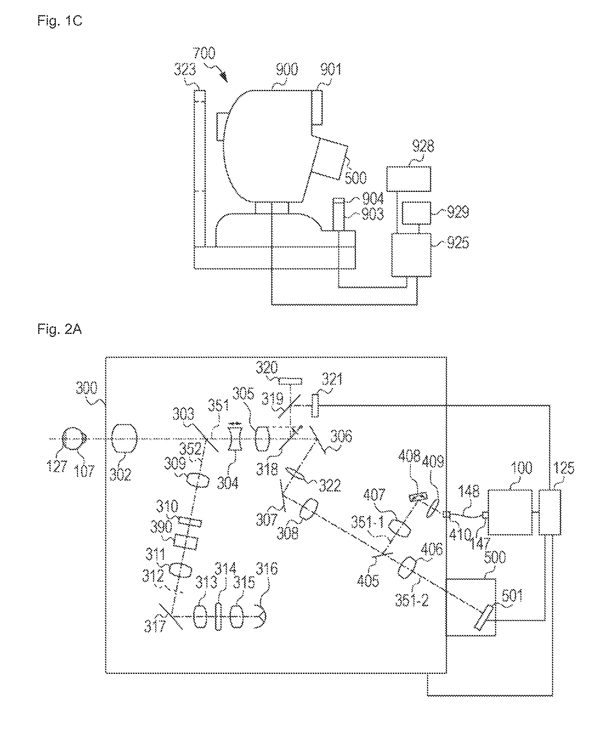
[0109]An overall configuration of the eyeground imaging apparatus of the third example will be described with reference to FIGS. 1B and 1C. FIG. 1B is a side view of an eyeground imaging apparatus 200 of the third example. The imaging apparatus 200 includes a tomographic-image pickup unit 100, a retinal-camera main unit 900, an adaptor 400, and a camera unit 500. The retinal-camera main unit 900, the adaptor unit 400, and the camera unit 500 are connected optically. The retinal-camera main unit 900 and the adaptor 400 are held to be movable relative to each other so that rough optical adjustment is possible. Furt...


PUM


Abstract

A tomographic-image pickup unit is controlled so as to capture a tomographic image in response to a signal input from a signal input unit. Then, a display unit is controlled so as to display the captured. tomographic image. An eyeground-image pickup unit is controlled so as to capture a two-dimensional image in response to a signal input from the signal input unit while the tomographic image. is displayed on the display unit. Therewith, the user can more easily perform imaging, and the time load on the subject is reduced.

Description

TECHNICAL FIELD[0001]The present invention relates to an eyeground imaging apparatus and a control method therefor, and more particularly, to an eyeground imaging apparatus used to acquire a surface image and a tomographic image of an eyeground of an eye to he examined, and a control method therefor.BACKGROUND ART[0002]In recent years, imaging apparatuses using optical coherence tomography (OCT) that utilizes interference of low coherent light (hereinafter also referred to as OCT apparatuses) have been put into practical use. Since an OCT apparatus can acquire a tomographic image only with a resolution substantially equivalent to the wavelength of light incident on an object to he examined, a tomographic image of a sample can he obtained with a high resolution. Particularly in the ophthalmologic field, the OCT apparatus is useful for obtaining a tomographic image of a retina at the eyeground.[0003]A composite apparatus using an OCT apparatus and a retinal camera (an apparatus for ca...

Claims


Application Information

Patent Timeline
Patent Type & Authority Patents(United States)
IPC IPC(8): A61B3/14A61B3/10
CPCA61B3/102A61B3/12A61B3/0058
Inventor MUTO, KENJINUMAJIRI, YASUYUKISUEHIRA, NOBUHITOSATO, MAKOTOSAKAGAWA, YUKIOKATAYAMA, AKIHIRO
Owner CANON KK
Why Eureka
Try Eureka