MEMS device connected to a substrate by flexible support structures

a technology of flexible support structure and micro-electromagnetic system, which is applied in the direction of fluid speed measurement, instruments, coatings, etc., can solve the problems of significant affecting the performance of micro-electromagnetic system devices, increasing the thermal and power budget of devices, increasing the cost, size, weight, etc., to reduce vibration transfer, reduce stress, and increase the size of devices

Active Publication Date: 2016-05-10
HRL LAB
View PDF8 Cites 10 Cited by
  • Summary
  • Abstract
  • Description
  • Claims
  • Application Information

AI Technical Summary

Benefits of technology

[0013]The present disclosure provides for assembling the MEMS to the substrate using flexible conductive mounts or support structures that can be fabricated with CMOS compatible wafer scale fabrication techniques and that only minimally increase the size of the device. The flexible support structures according to the present disclosure are capable of flexing to reduce stress formed by thermal variation, as well as forming a low frequency spring that may be used to reduce the transfer of vibrations to the MEMS.

Problems solved by technology

The performance of Micro Electro Mechanical Systems (MEMS) devices is significantly impacted by environmental effects, most typically thermal fluctuations / variations and vibrations.
This requirement adds the need for a compensation circuit and / or ovenization, significantly increasing the thermal and power budget of the devices.
Quartz devices are one of many precision mechanical sensors that suffer from environmental effects.
Over the years, at the macro scale, designs for flexible mounting, ovenization, and material selections have matured, albeit with increase in cost, size, weight, and power (cSWAP).
At the micro scale the technology has yet to mature, due to a different set of challenges in fabrication and design.
A problem arising with MEMS assembly 20 is that, due to the stiff nature of the bond typically created between connection pads 12 and 16, stress and strain may form with thermal variations, due to thermal expansion mismatch between the materials of MEMS 10 and substrate 18.
Furthermore, due to the stiff nature of the connection, mechanical vibrations are easily transferred directly from the substrate to the device, thus reducing performance of the device.
However, this process is a slow and manually intensive task that increases time and cost of production.
However, such designs generally make fabrication and operation of the device more difficult.
It is noted however that the design, manufacturing, and operation of such platforms at the micro scale add a significant amount of complexity and cost.

Method used


Image

  • MEMS device connected to a substrate by flexible support structures
  • MEMS device connected to a substrate by flexible support structures
  • MEMS device connected to a substrate by flexible support structures

Examples


Embodiment Construction

[0043]In the following description, numerous specific details are set forth to clearly describe various specific embodiments disclosed herein. One skilled in the art, however, will understand that the presently claimed invention may be practiced without all of the specific details discussed below. In other instances, well known features have not been described so as not to obscure the invention.

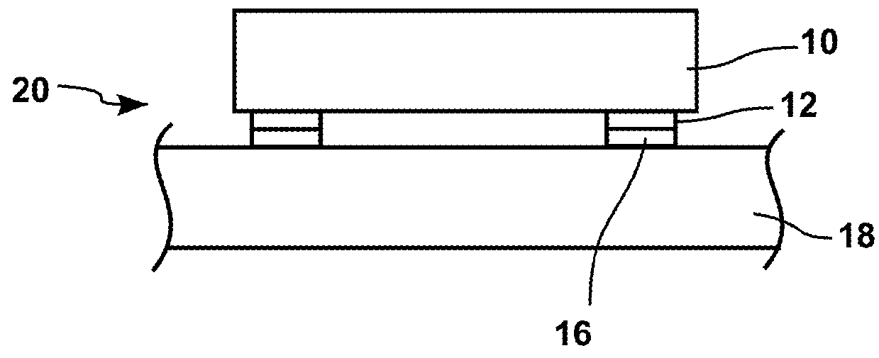
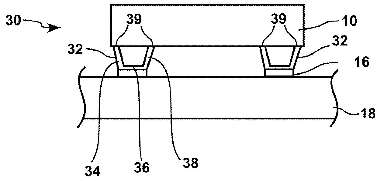
[0044]FIG. 3A shows a cross section of a MEMS assembly 30 comprising MEMS device 10 attached to substrate 18 by the bonding of flexible support structures 32 pads on connection pads 16. A handle of MEMS 10 was removed after the bonding of flexible support structures 32 on connection pads 16, as detailed hereafter. Substrate 18 can be as substrate 18 of FIG. 1. MEMS 10 and substrate 18 can for example be a quartz resonator and a base substrate such as described in U.S. Pat. No. 7,237,315, which is hereby incorporated by reference.

[0045]As detailed hereafter, for example in relation with FIGS. ...


PUM

PropertyMeasurementUnit
thicknessaaaaaaaaaa
thicknessaaaaaaaaaa
flexibleaaaaaaaaaa

Abstract

A MEMS assembly comprising a substrate and a MEMS device; wherein the MEMS device is connected to the substrate by at least two flexible support structures made in a conductive layer formed on a first portion of one of the substrate and the MEMS.

Description

REFERENCE TO A CONTRACT[0001]This disclosure relates to work performed under Government contract No. HR0011-10-C-0109: Dynamics-Enabled Frequency Sources.INCORPORATION BY REFERENCE[0002]The present disclosure relates to U.S. Pat. No. 7,237,315, issued on Jul. 3, 2007, which is hereby incorporated by reference.TECHNICAL FIELD[0003]This disclosure relates to a flexible mount for attaching a micro electro mechanical systems (MEMS) devices to a substrate.BACKGROUND[0004]The performance of Micro Electro Mechanical Systems (MEMS) devices is significantly impacted by environmental effects, most typically thermal fluctuations / variations and vibrations. For example, in the field of Quartz resonators (oscillators, monolithic filters, etc.) the center frequency must be maintained over a −40 C and 80 C temperature range to within parts per million (ppm) and in some cases parts per billion (ppb) (See for example: J. R. Vig, “Quartz Crystal Resonators and Oscillators For Frequency Control and Tim...

Claims


Application Information

Patent Timeline
Patent Type & Authority Patents(United States)
IPC IPC(8): B81B7/00B81C1/00
CPCB81B7/0006B81C1/00301B81B7/0019B81B7/0016B81B7/0048B81B2207/07
Inventor PERAHIA, RAVIVNGUYEN, HUNGJOYCE, RICHARD J.
Owner HRL LAB
Why Eureka
Try Eureka