Propshaft holding tool

a tool and propshaft technology, applied in the field of removal tools, can solve the problems of assembly slippage, improper torque of mounting bolts, and difficulty in assembling a front propshaft to the vehicle drivetrain, and achieve the effects of minimizing the chance of the flange moving during installation, avoiding the assembler's hand pinched during assembly, and high torqu

Active Publication Date: 2016-05-17
GM GLOBAL TECH OPERATIONS LLC
View PDF14 Cites 2 Cited by
  • Summary
  • Abstract
  • Description
  • Claims
  • Application Information

AI Technical Summary

Benefits of technology

[0007]An advantage of an embodiment is that a propshaft holding tool secures the propshaft in place while installing and applying torque to mounting bolts, even when a relatively high torque is required. This propshaft holding tool secures the propshaft during assembly while not nicking, denting or scuffing the propshaft or damaging any vehicle components, such as a vehicle frame or transmission. Moreover, the propshaft holding tool assures proper torque is achieved on the bolts during installation. It also minimizes the chances of the flanges moving during installation, thus assuring a proper installation and avoiding the assembler having his hand pinched during assembly. The propshaft holding tool also allows for use on different models of vehicle that may have somewhat different diameter propshafts.

Problems solved by technology

While assembling automotive vehicles, and in particular, four wheel drive trucks, some difficulties may be encountered in assembling a front propshaft to the vehicle drivetrain.
If not properly secured against rotation during installation of the mounting bolts, the proper torque of the mounting bolts may not be achieved, and moreover, the assembly may slip, pinching the installer's hand as the flange slips.
However, this is a very time consuming process, which is undesirable for assembling a vehicle.
Moreover, circumventing portions of this process may provide false torque readings on the fasteners.
However, this can cause dents and nicks in the surface of the propshaft, which may allow for rust on the propshaft at these locations.
This may also lead to false torque readings during installation, or even to allowing for flange turning during installation, both undesirable situations.

Method used


Image

  • Propshaft holding tool
  • Propshaft holding tool
  • Propshaft holding tool

Examples


Embodiment Construction

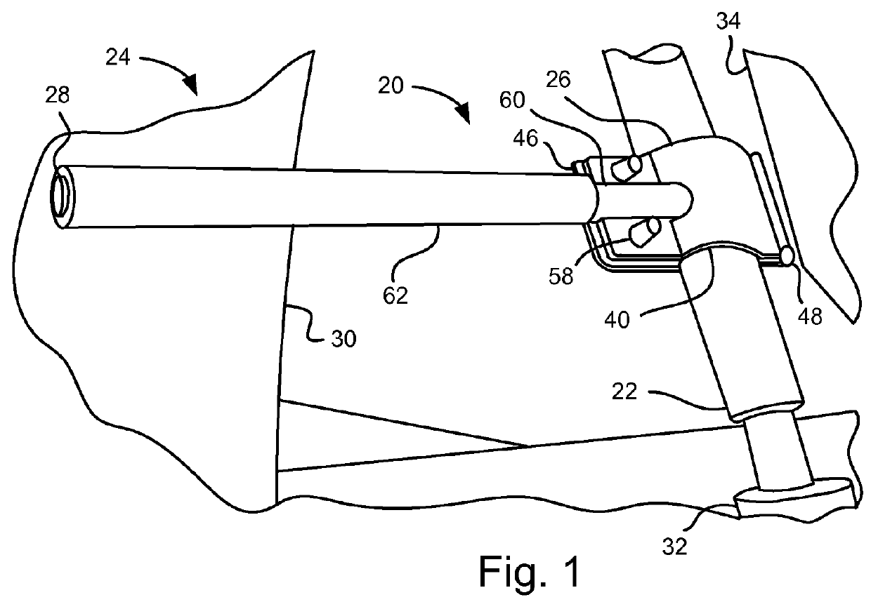
[0014]Referring to FIG. 1, a propshaft holding tool 20 is secured to a front propshaft 22 of a vehicle, referred to generally at 24. The propshaft holding tool 20 has a head 26 that is secured to the propshaft 22. A handle (arm) 28 extends from the head 26 and engages a portion of a vehicle frame 30. A portion of one of the two flanges 32 (mounting bolts not shown) at one end of the propshaft 22 and a portion of a transmission 34 is also shown.

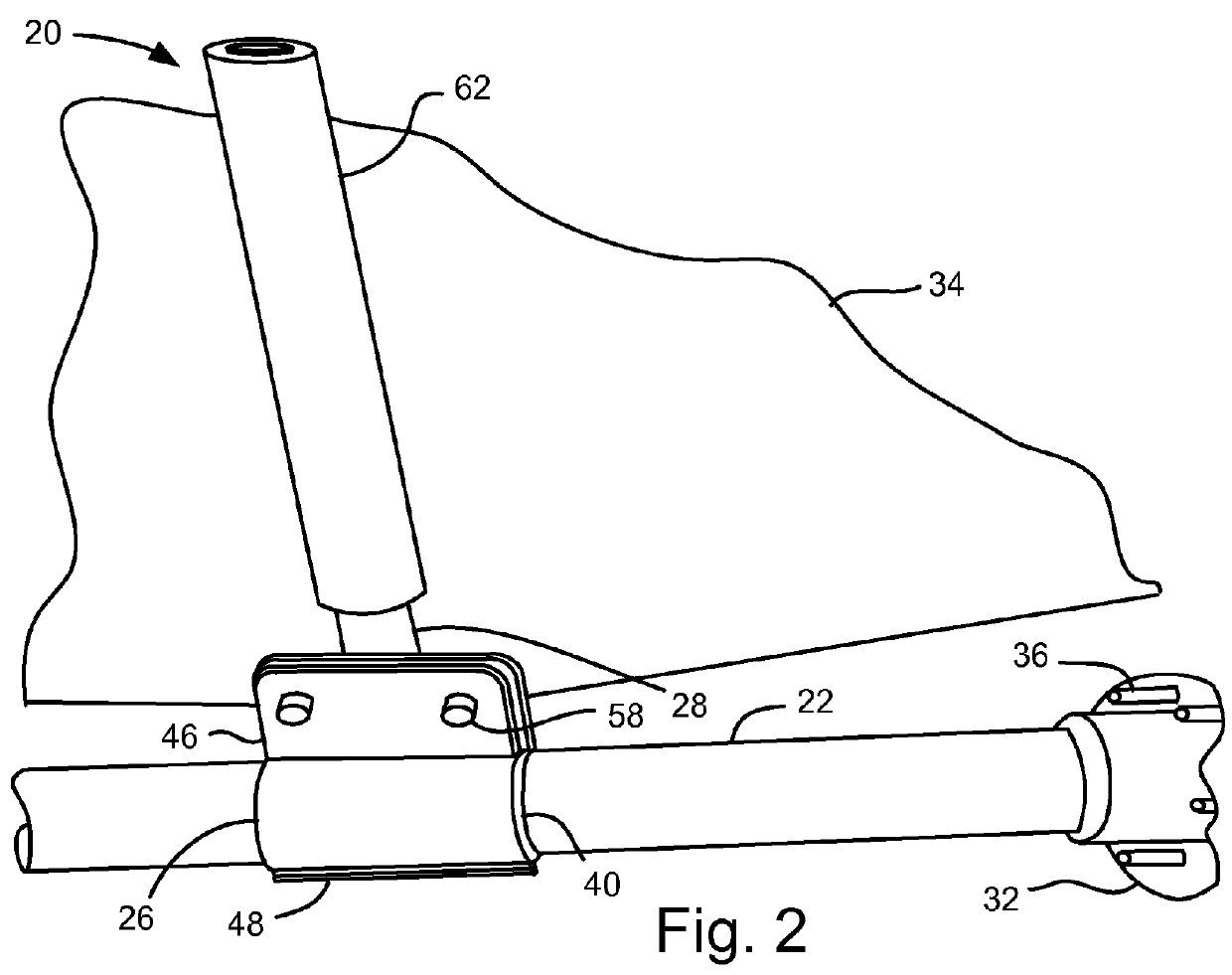
[0015]FIG. 2 shows the head 26 of the propshaft holding tool 20 secure to the propshaft 22, with the handle 28 engaging the transmission 34. A portion of one of the two flanges 32 is also shown, with mounting fasteners (bolts) 36 extending from the flange 32.

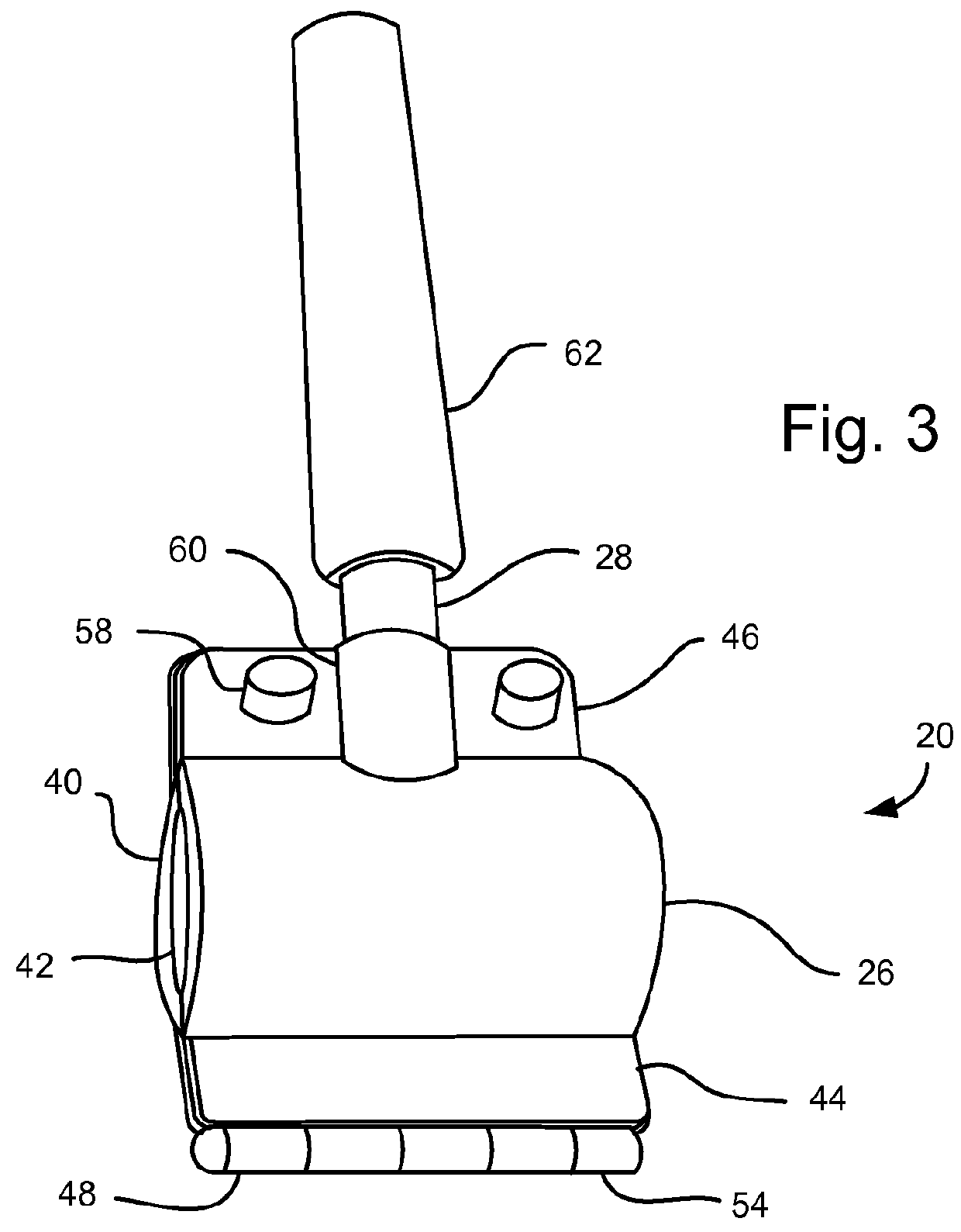
[0016]The propshaft holding tool 20 will be discussed in more detail, with reference to FIGS. 1-5. The head 26 includes a pair of semi-cylindrical main bodies 40 that face each other to form a channel 42. Each main body 40 includes a hinge flange 44 extending generally perpendicular from a...


PUM

PropertyMeasurementUnit
resilientaaaaaaaaaa
torqueaaaaaaaaaa
rotationaaaaaaaaaa

Abstract

A holding tool for releasably securing a shaft from rotation relative to the holding tool. The holding tool may have a head including a pair of semi-cylindrical main bodies, each head having a hinge flange extending from a respective first end of the main body and a bolt flange extending from a respective, opposed second end of the main body, with each bolt flange including a fastener hole; a hinge pivotally securing the hinge flanges together; a fastener received through the fastener hole and selectively biasing the bolt flanges toward one another; a pair of semi-cylindrical shaped resilient inserts, each secured to an inner surface of the main bodies, defining a cylindrical channel to receive the shaft; and a handle extending generally radially outward from the head. The holding tool may be used to secure a propshaft to a vehicle.

Description

BACKGROUND OF INVENTION[0001]The present invention relates generally to a removable tool for preventing a shaft from rotating, and more particularly a tool for holding a propshaft from rotating during vehicle assembly or repair.[0002]While assembling automotive vehicles, and in particular, four wheel drive trucks, some difficulties may be encountered in assembling a front propshaft to the vehicle drivetrain. The propshaft is assembled to the front axle and transfer case. Particularly in situations where a propshaft is being repaired or replaced, or when the front propshaft is installed off of a vehicle assembly line, a means for holding the propshaft while installing six mounting bolts per flange is needed. In particular situations, the flanges securing the propshaft to the front axle and to the transfer case may be flush flanges to the front propshaft. Such a configuration may have relatively high torque requirements for the mounting bolts in order to achieve the desired clamp load...

Claims


Application Information

Patent Timeline
Patent Type & Authority Patents(United States)
IPC IPC(8): B23P11/00B25B5/14F16C3/02B25B5/10B25B23/00B25B27/00
CPCB25B5/14B25B5/10B25B5/103B25B5/147B25B23/0085B25B27/0035F16C3/02F16C2322/50Y10T29/49998
Inventor MARKWARDT, TIMOTHY J.
Owner GM GLOBAL TECH OPERATIONS LLC
Why Eureka
Try Eureka