
Load lifting assembly

a technology of load lifting and assembly, which is applied in the direction of lifting frames, lifting devices, building lifts, etc., can solve the problems of lack of flexibility in lifting loads of various sizes, difficulty in assembling, mounting and requiring a lot of maintenance, and manual lifting of loads of various shapes, sizes and weights by laborers, etc., to improve the functionality of the unit, improve the effect of the unit and the cost reduction

Active Publication Date: 2016-05-17
UNIVERSITI BRUNEI DARUSSALAM
View PDF15 Cites 0 Cited by
  • Summary
  • Abstract
  • Description
  • Claims
  • Application Information

AI Technical Summary

Benefits of technology

The invention is a load lifting assembly that is easy to assemble, uses low-cost materials, and is flexible in nature. The assembly can be modified based on the weight and type of load being lifted, and different numbers of bearings and bars can be used for heavier or lighter loads. The components of the assembly can be made from various materials like steel, stainless steel, aluminum, or other materials to create a strong and durable assembly. The screws used can be replaced with high tensioned screws for better stability. Overall, the assembly provides an efficient, cost-effective, and flexible solution for lifting and transporting loads.

Problems solved by technology

The task of carrying loads of various shapes, sizes and weights manually by laborers is a physically challenging and time consuming process.
Another drawback is that these assemblies are difficult to assemble, mount and require a lot of maintenance.
Also, they lack the flexibility in terms of lifting the loads of various sizes and are expensive to manufacture.
Further, they exhibit a lot of friction which hampers their performance.

Method used


Image

  • Load lifting assembly
  • Load lifting assembly
  • Load lifting assembly

Examples


Embodiment Construction

[0023]In the detailed description of the present invention, numerous specific details are described to provide a thorough understanding of the various embodiments of the present invention. However, a person skilled in the relevant art will recognize that an embodiment of the present invention can be practiced without one or more of the specific details, or with other apparatuses, systems, assemblies, methods, components, materials, parts, and / or the like. In other instances, well-known structures, materials, or operations are not specifically shown or described in detail to avoid obscuring aspects of embodiments of the present invention.

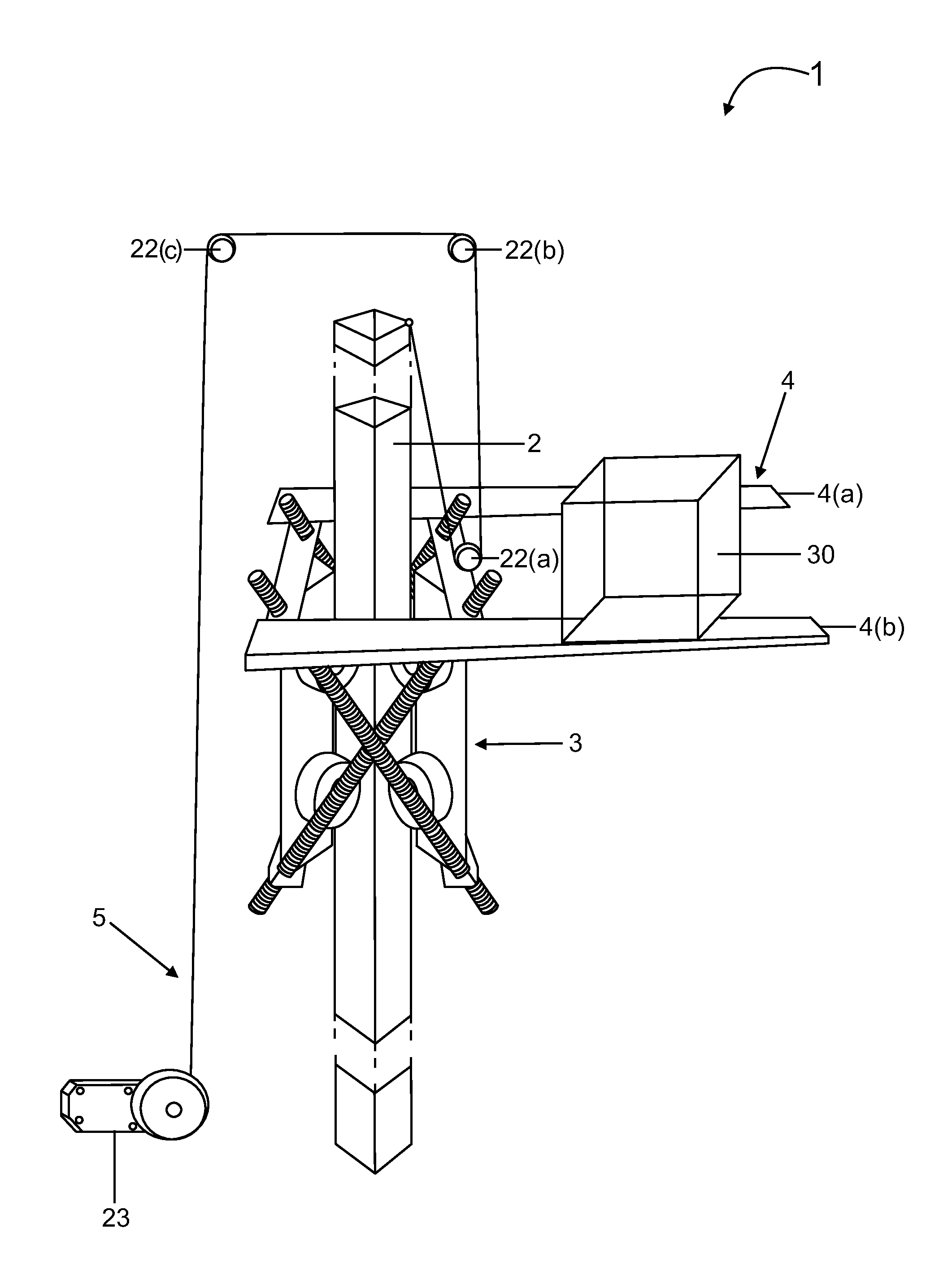
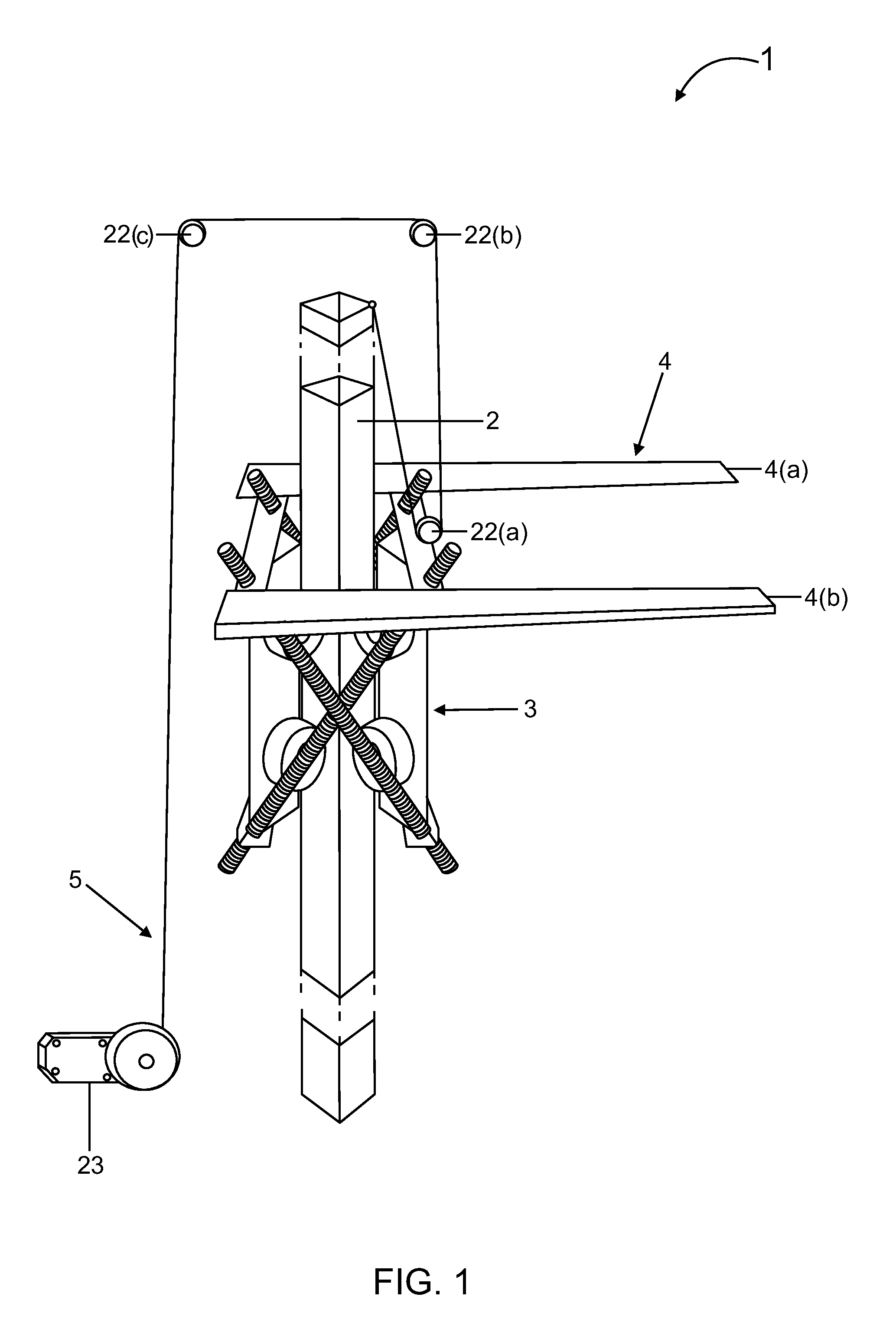
[0024]The invention relates to a load lifting assembly 1 as illustrated in FIG. 1. The load lifting assembly 1 comprises a pole 2, a lifting unit 3, a load transporting unit 4 and a driving unit 5. Preferably, the pole 2 has a diamond shape and is fixed at its base.

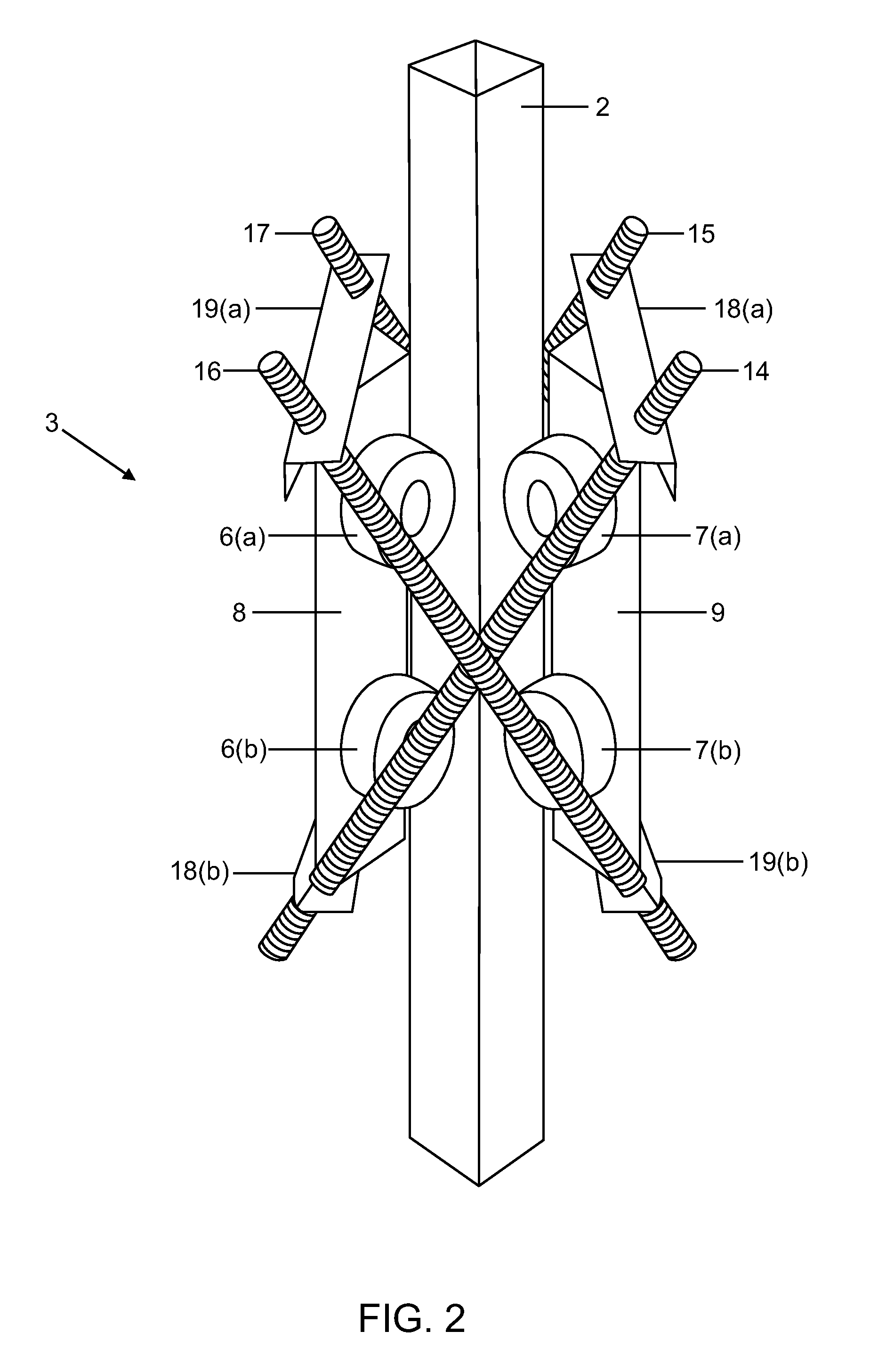
[0025]As illustrated in FIG. 2, the lifting unit 3 comprises a plurality of bars 8, 9 ...


PUM


Abstract

The invention relates to a load lifting assembly to lift and transport the loads. The assembly comprises a fixed pole and a lifting unit capable of moving longitudinally along the pole. The assembly further comprises a load transporting unit coupled to the lifting unit and a driving unit to provide the motive force to the load transporting unit.

Description

FIELD OF THE INVENTION[0001]The present invention relates to an assembly to lift and transport loads.BACKGROUND OF THE INVENTION[0002]Lifting and transportation of loads from one place to another is a regular routine in various industries including textile, mechanical, civil, cargo, automotive, the plastic industry, the woodworking industry, the foodstuffs industry and the drinks industry. Load lifting ventures involves transporting loads manually or with the help of load lifting devices. The task of carrying loads of various shapes, sizes and weights manually by laborers is a physically challenging and time consuming process.[0003]There are various assemblies available in the prior art for lifting purposes like an assembly having clamping jaws connected by a rod and moving on a column, the lower jaw carries the load and the upper jaw is connected through a lever to an operating lever which is reciprocated to cause the load to climb the column, the jaws gripping the column alternate...

Claims


Application Information

Patent Timeline
Patent Type & Authority Patents(United States)
IPC IPC(8): B66B9/00B66F9/08B66F7/02
CPCB66F7/02B66F9/08
Inventor CHONG, KIM ONNOSMAN, ISYRAH FAHMIFOO, LIM REN
Owner UNIVERSITI BRUNEI DARUSSALAM
Features
  • Generate Ideas
  • Intellectual Property
  • Life Sciences
  • Materials
  • Tech Scout
  • Unparalleled Data Quality
  • Higher Quality Content
  • 60% Fewer Hallucinations
Learn More