System and method for monitoring a fluid

a technology for monitoring systems and fluids, applied in the field of fluid monitoring, can solve the problems of reduced inability to detect the degradation process in time, and achieve the effect of entanglement of the fluid, reducing the cost of maintenance, and reducing the service life of industrial machinery

Active Publication Date: 2016-05-17
ATTEN2 ADVANCED MONITORING TECH S L U
View PDF6 Cites 9 Cited by
  • Summary
  • Abstract
  • Description
  • Claims
  • Application Information

AI Technical Summary

Problems solved by technology

The reduction in the service life of this industrial machinery often gives rise to unnecessary maintenance costs.
Current ‘off-line’ measurement methodologies (oil sample analysis in the laboratory) do not provide a sufficiently early detection of the degradation process due to the low frequency with which these measurements are usually taken.
. . ) this control methodology entails a significant logistical and financial burden.
Oil heating, for example, can be a sign that the machine is not operating in optimum conditions, and the presence of particles in the oil may indicate a future failure or considerable wear in the lubricated components.
However, filtering systems do not act on the root cause of the problem, and instead are limited to reducing the consequences of particle generation, whose presence in the lubrication system could accentuate the generation of more serious problems.
At the same time, filtering systems present a series of limitations: they can become clogged or saturated, not being capable of removing any more particles.
The main problem with these systems is the presence of water or air bubbles, which are counted as particles.
However, the system of U.S. Pat. No. 5,572,320 is not capable of discriminating between particle shapes.
Also, the measuring cell of U.S. Pat. No. 5,572,320 consists of a moving part that positions the oil in a specific place, and this complicates development and can be an important source of errors.
However, the device of this patent does not allow a homogenous lighting to be provided over an inspection area that is greater than the beam of light itself.
Another of the parameters that it could be interesting to monitor in lubricating oil is the bubble content in the system, since this can be indicative of foam generation in the oil and air retention in the system, which is undesirable.

Method used


Image

  • System and method for monitoring a fluid
  • System and method for monitoring a fluid
  • System and method for monitoring a fluid

Examples


Embodiment Construction

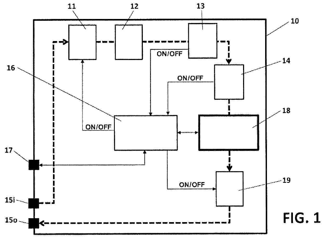
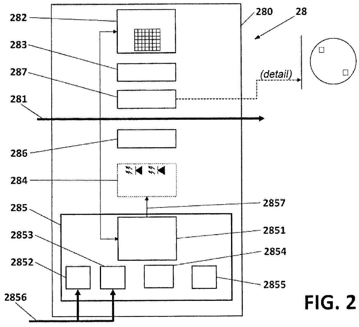
[0021]The present invention attempts to resolve the drawbacks mentioned above by means of a system for inspecting oil, which comprises a cell through which oil flows along a pipe. The system comprises inside said cell: a lighting system based on at least one LED diode and configured to supply a beam of white light to the flow of oil; a diffuser situated between the lighting system and the flow of oil, configured to provide homogeneous lighting in the lit area; an image capture system situated on the opposite side of the pipe through which the oil flows in respect of the lighting system and configured to capture a sequence of images of the oil that flows inside said pipe; a lens situated between the image capture system and the oil flow, configured to focus the captured images; a calibration device situated between the lens and the oil flow; a processor configured to process said sequence of images and to determine the presence of particles and a value for the oil degradation.

[0022]P...


PUM

PropertyMeasurementUnit
sizeaaaaaaaaaa
areaaaaaaaaaaa
distanceaaaaaaaaaa

Abstract

System (18, 28) for inspecting oil, which comprises a cell (280) through which oil (281) flows through a pipe. Inside said cell (280) the system comprises a lighting system (284) based on at least one LED diode and configured to supply a beam of white light to the flow of oil (281); a diffuser (286) situated between the lighting system (284) and the flow of oil (281), configured to provide homogeneous lighting to the lit area; an image capture system (282, 382) situated on the opposite side of the pipe through which the oil (281) flows in respect of the lighting system (284) and configured to capture a sequence of images of the oil which flows inside said pipe; a lens (283) situated between the image capture system (282) and the flow of oil (281), configured to focus the captured images; a calibration device (287) situated between the lens (283) and the flow of oil (281); a processor (2851) configured to process said sequence of images and to determine the presence of particles and bubbles and a degradation value of the oil.

Description

TECHNICAL FIELD[0001]The present invention relates to the field of fluid monitoring for determining the general condition of fluids from the point of view of their degradation and also particle content. More specifically, it relates to the field of oil monitoring, in particular lubricating oils, in order to obtain through said monitoring their state of degradation, and also to obtain information on the machinery lubricated by said oils on the basis of their particle content.BACKGROUND OF THE INVENTION[0002]Industrial machinery, whether engines or power generating turbines, compressors, multipliers, etc. undergo unforeseen shutdowns and failures, often associated to aspects related to lubrication. The reduction in the service life of this industrial machinery often gives rise to unnecessary maintenance costs. Current ‘off-line’ measurement methodologies (oil sample analysis in the laboratory) do not provide a sufficiently early detection of the degradation process due to the low freq...

Claims


Application Information

Patent Timeline
Patent Type & Authority Patents(United States)
IPC IPC(8): G01N33/28G01N21/25G01N21/85
CPCG01N15/0227G01N21/274G01N33/2888G01N21/85G01N21/25G01N2015/0053G01N2015/0011G01N2201/062G01N2201/0631G01N2201/0634
Inventor GORRITXATEGI, ENEKOMABE, JON
Owner ATTEN2 ADVANCED MONITORING TECH S L U
Why Eureka
Try Eureka