Coupling device

a technology of coupling device and tool holder, which is applied in the direction of sleeve/socket joint, turning apparatus, stone-like material working apparatus, etc., can solve the problems of time-consuming and labor-intensive to secure the tool holder, difficult to later unscrew the tool holder from the spindle, and question run the risk of being damaged

Active Publication Date: 2016-05-24
JOHNSEN ANDERS
View PDF9 Cites 2 Cited by
  • Summary
  • Abstract
  • Description
  • Claims
  • Application Information

AI Technical Summary

Benefits of technology

[0010]a locking sleeve which is rotatably arranged on the outside of the female-shaped coupling part outwardly of the internally cone-shaped section and the locking balls, the locking sleeve being rotatable to and fro between a releasing position, in which the locking sleeve allows the respective locking ball to be displaced radially to a retracted position while allowing a mutual axial displacement between said coupling parts, and a locking position, in which the locking sleeve forces the respective locking ball to assume an advanced position with the locking ball extending through the inwards facing opening of the associated hole and down into the groove in the externally cone-shaped section while preventing a mutual axial displacement between said coupling parts.
[0012]With the coupling device according to the invention, the tool holder is in a rapid and simple manner guided into the correct position in relation to the spindle under the effect of the mutually co-operating cone-shaped sections of said male-shaped and female-shaped coupling parts. The tool holder may then with a simple manipulation be locked to the spindle by rotating the locking sleeve so that the locking balls of the female-shaped coupling part is brought into locking engagement with the groove in the male-shaped coupling part and thereby prevent a mutual axial displacement between the tool holder and the spindle. The tool holder may with a corresponding simple manipulation be released from the spindle by rotating the locking sleeve in the opposite direction so that the locking balls will be free to be displaced radially out of the groove in the male-shaped coupling part and thereby allow an axial displacement of the tool holder away from the spindle. Owing to the fact that that the guide members which act against the locking balls in order to lock these in the advanced position are radially springing, the manoeuvring of the locking sleeve from the releasing position to the locking position and from the locking position to the releasing position is facilitated. By using radially springing guide members, the tolerance requirements on the locking sleeve and its guide members will in addition be comparatively low, which facilitates the manufacturing of the locking sleeve.
[0013]According to an embodiment of the invention, the locking sleeve comprises a ring-shaped holder, which extends around the female-shaped coupling part and via which the locking sleeve slideably bears against the envelope surface of the female-shaped coupling part, the guide members being springingly fixed to this ring-shaped holder. By having the guide members springingly suspended jointly in a ring-shaped holder, the desired radially springing characteristic of the guide members can be achieved in a simple manner.
[0017]Hereby, a mutual rotation between the tool holder and the spindle when connected to each other is prevented in a simple and efficient manner.

Problems solved by technology

A disadvantage with such a threaded coupling is that it might be time-consuming to secure the tool holder to the spindle by screwing.
It might also be time-consuming and difficult to later unscrew the tool holder from the spindle, since the threaded coupling tightens itself during the drilling procedure.
Furthermore, the threads in question run the risk of being damaged, which can make it even more difficult and in the worst case impossible to secure the tool holder to the spindle by screwing.

Method used


Image

  • Coupling device
  • Coupling device
  • Coupling device

Examples


Embodiment Construction

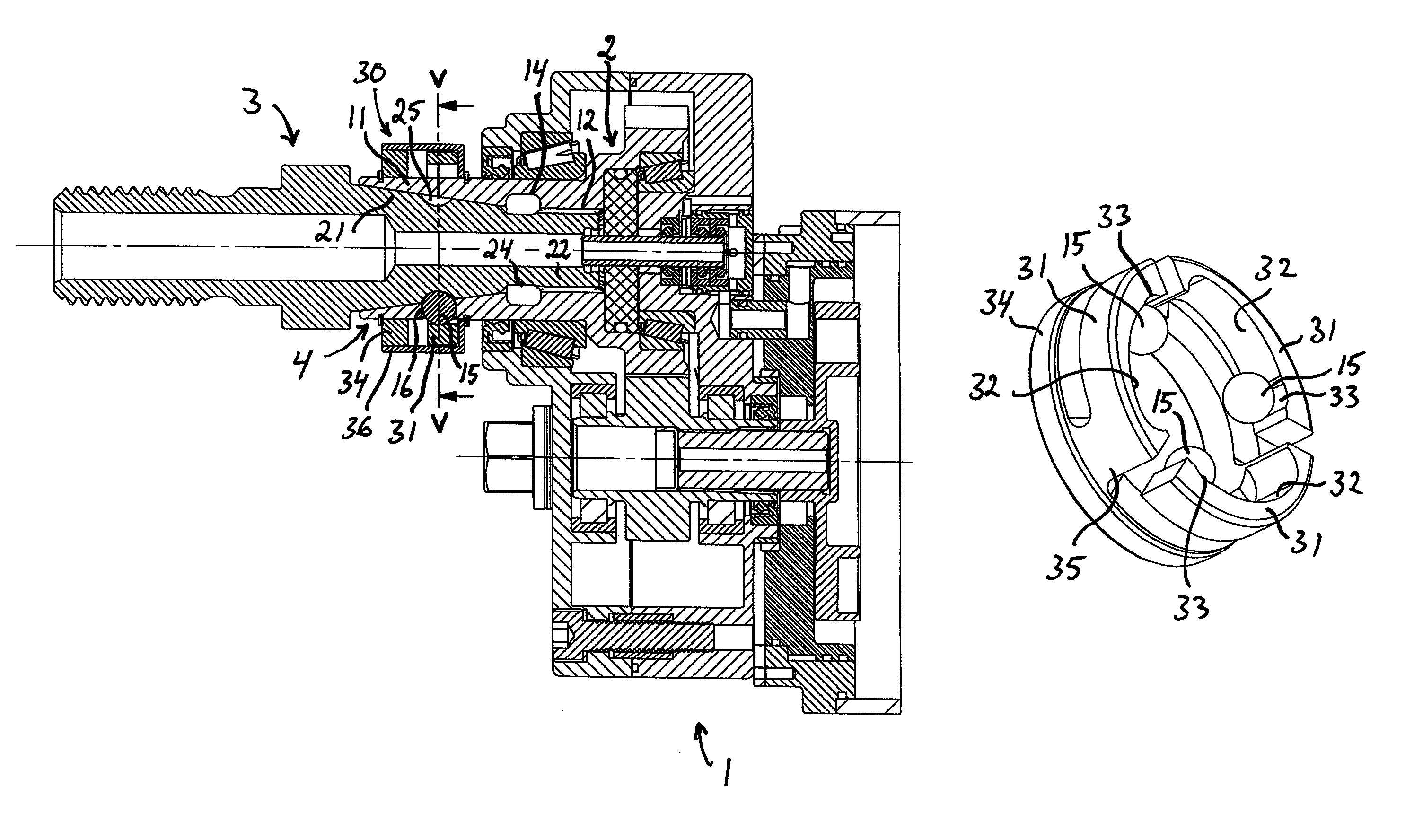
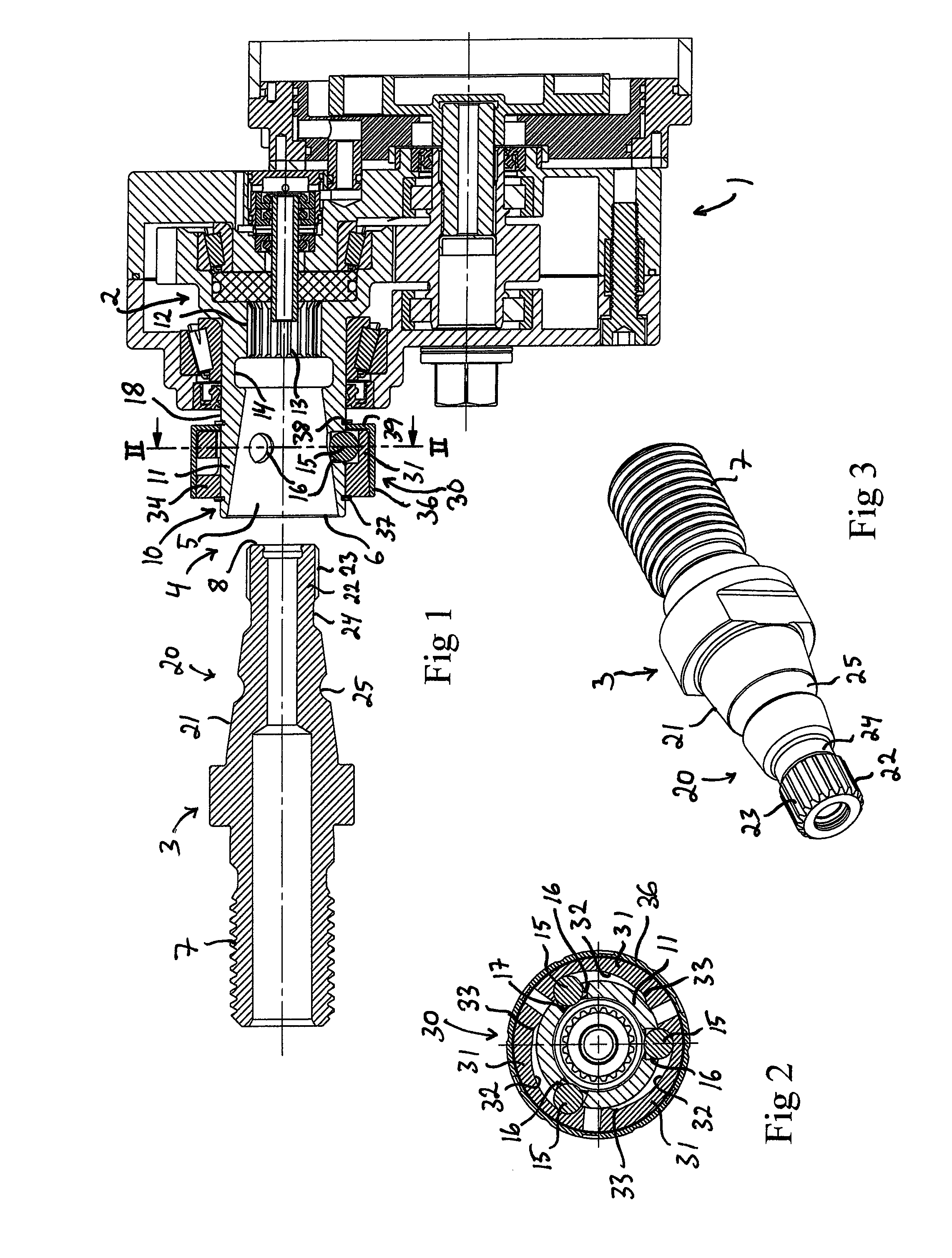
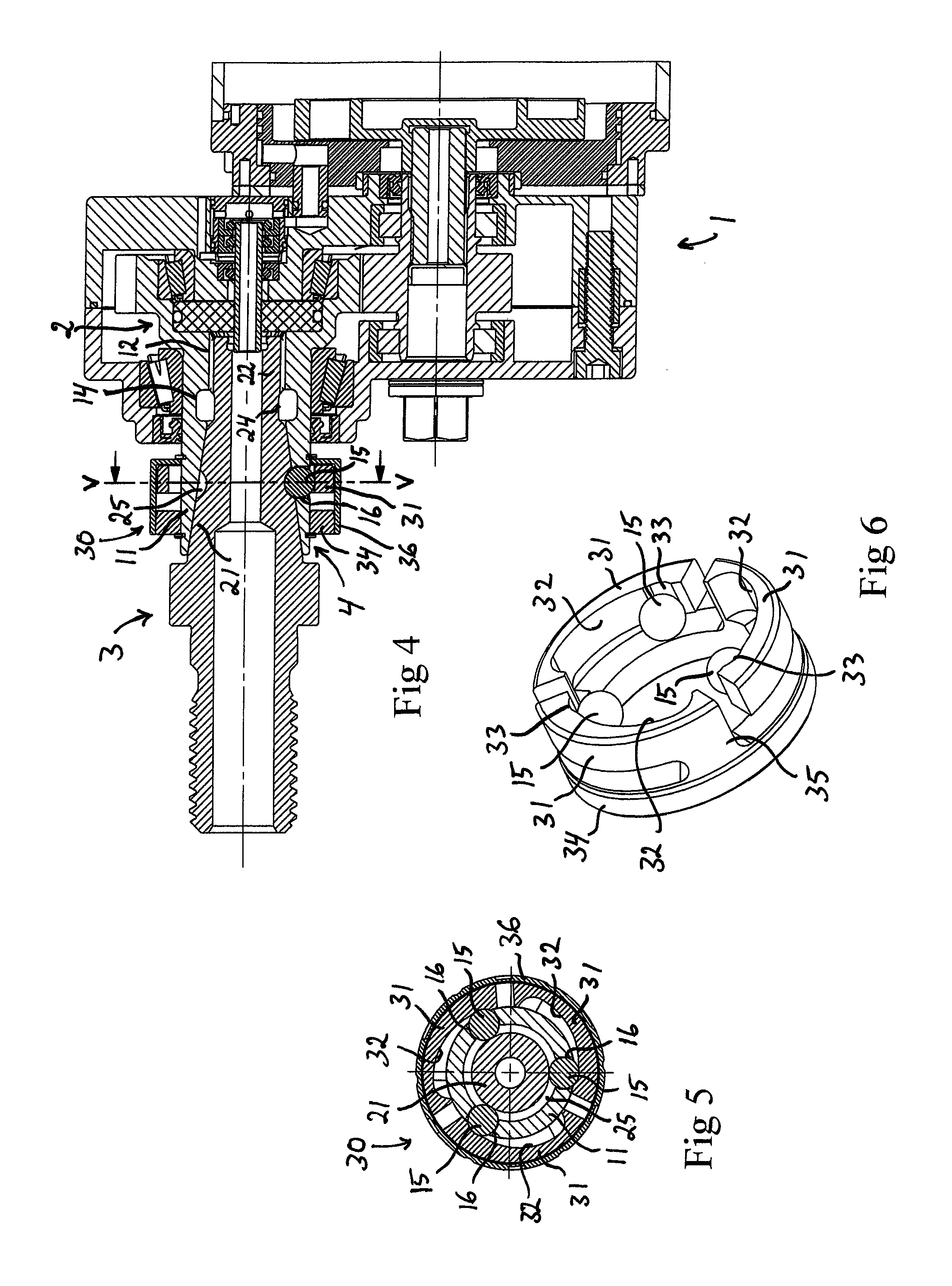
[0027]FIG. 1 shows a part of a machining machine 1 with an output shaft in the form of a spindle 2 and a tool holder 3, which is connectable to the spindle. The spindle 2 is rotatably mounted and arranged to be rotated under the effect of a drive motor (not shown) of the machining machine. The tool holder 3 and the spindle 2 are connectable to each other by means of a coupling device 4 according to the present invention. The spindle 2 is hollow and provided with a recess 5 which extends axially into the spindle 2 from an outwards facing opening 6 at the outer end of the spindle.

[0028]The coupling device 4 comprises a female-shaped coupling part 10 which is fixedly connected to the spindle 2, and a corresponding male-shaped coupling part 20 which is fixedly connected into the tool holder 3. The female-shaped coupling part 10 is provided with an internally cone-shaped section 11. The male-shaped coupling part 20 is provided with a corresponding externally cone-shaped section 21, which...


PUM

PropertyMeasurementUnit
axial displacementaaaaaaaaaa
concave shapeaaaaaaaaaa
torqueaaaaaaaaaa

Abstract

A coupling device for coupling together a tool holder (3) with a rotatable spindle (2) of a machining machine. The coupling device comprises: —a female-shaped coupling part (10) with an internally cone-shaped section (11) and a male-shaped coupling part (20) with an externally cone-shaped section (21); —an annular groove (25) arranged in the externally cone-shaped section; —locking balls (15), which are radially displaceable in radial holes (16) in the internally cone-shaped section; and —a locking sleeve (30), which is arranged on the outside of the female-shaped coupling part and which is rotatable between a releasing position, in which the locking balls can be displaced radially to a retracted position while allowing a mutual axial displacement between the coupling parts, and a locking position, in which the locking balls are kept in engagement in said groove while preventing a mutual axial displacement between the coupling parts. The locking sleeve is provided with radially springing guide members (31), which co-operates with a respective locking ball.

Description

FIELD OF THE INVENTION AND PRIOR ART[0001]The present invention relates to a coupling device for coupling together a tool holder with a rotatable spindle of a machining machine.[0002]In a drilling machine of heavier type for making of holes in concrete or other hard materials, a drilling tool, for instance in the form of a drill bit, is often detachably attached to the output shaft of the drilling machine, the so-called spindle, by means of a tool holder which is secured by screwing to the spindle by engagement between a thread on the tool holder and a corresponding thread on the spindle. A disadvantage with such a threaded coupling is that it might be time-consuming to secure the tool holder to the spindle by screwing. It might also be time-consuming and difficult to later unscrew the tool holder from the spindle, since the threaded coupling tightens itself during the drilling procedure. Furthermore, the threads in question run the risk of being damaged, which can make it even more...

Claims


Application Information

Patent Timeline
Patent Type & Authority Patents(United States)
IPC IPC(8): B23B31/107B28D7/00B23B31/00B23B31/22
CPCB28D7/00B23B31/006B23B31/1071B23B31/22B23B2231/026B23B2231/0264Y10T279/17701Y10T279/17717Y10T279/3493
Inventor JOHNSEN, ANDERS
Owner JOHNSEN ANDERS
Why Eureka
Try Eureka