Post-frame footing assembly and vertical post

a technology of vertical posts and footings, applied in the direction of buildings, buildings, constructions, etc., to achieve the effect of improving the installation and structural capability of vertical posts

Active Publication Date: 2016-05-24
WAGLER BENNIE R
View PDF29 Cites 7 Cited by
  • Summary
  • Abstract
  • Description
  • Claims
  • Application Information

AI Technical Summary

Benefits of technology

[0014]In view of the foregoing disadvantages inherent in the known types of post-frame construction techniques now present in the prior art, the present invention provides a new post-frame construction assembly that greatly improves installation and structural capability of a vertical post in structures built using post-frame construction.
[0017]Another object of the present invention is to provide post-frame construction assembly having a footer assembly that allows for movement of the vertical post within the excavated hole to facilitate proper alignment of the vertical post with adjacent posts and the required location of the vertical post relative to the structure to be supported.
[0018]Yet another object of the present invention is to provide post-frame construction assembly that increases the load capacity of a vertical post in post-frame construction structures, whereby vertical uplift load, vertical downward load, and side loads are transferred to the footing assembly.
[0019]Another object of the present invention is to provide post-frame construction assembly that improves installation of vertical posts during construction, improving efficiency of installation and accounting for minor misalignments during construction.

Problems solved by technology

Specifically, much of the prior art relates to general column or post support, and not to assemblies that provide for positional adjustment or improved loading capacity when supporting post-frame construction columns within an excavated and backfilled hole.
As noted above, the Egan, Jr. device is related to a column support that improves the foundation upon which the utility pole rests, but is not adapted for post-frame construction, for facilitating positional adjustment of the pole, or for improving load capacity at the base of the pole.

Method used


Image

  • Post-frame footing assembly and vertical post
  • Post-frame footing assembly and vertical post
  • Post-frame footing assembly and vertical post

Examples


Embodiment Construction

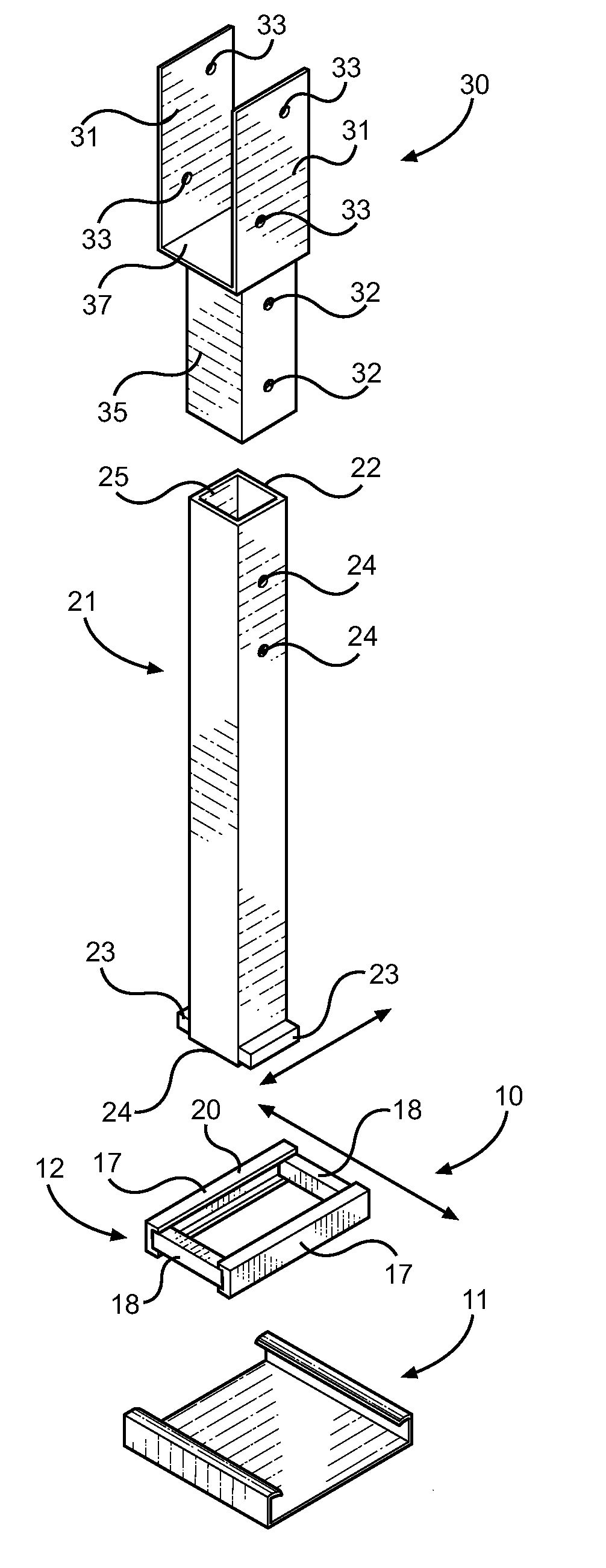
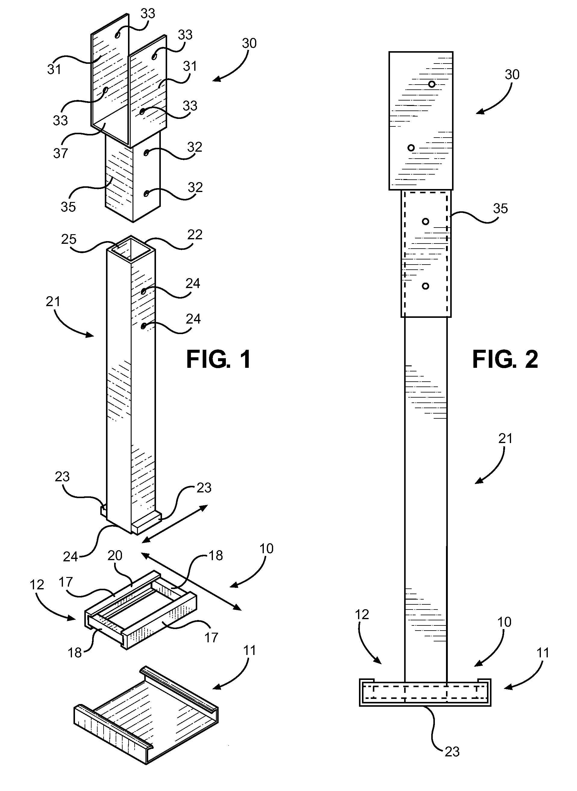
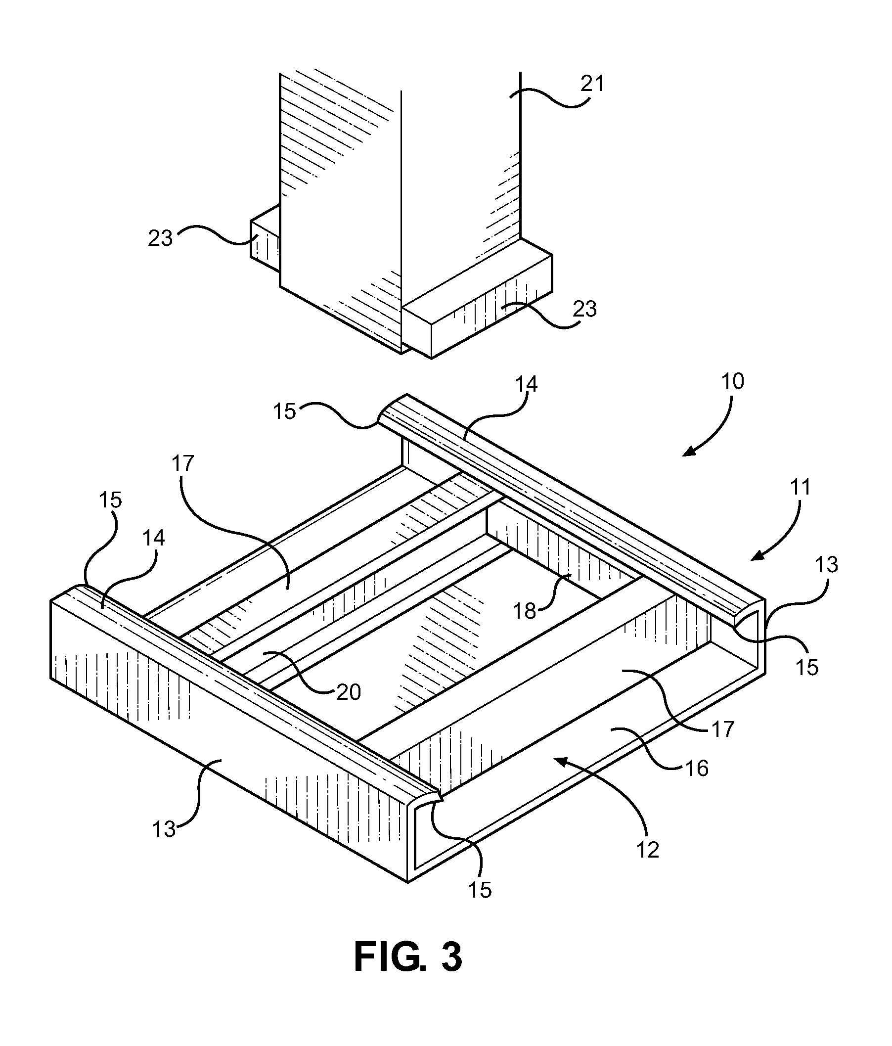
[0027]Reference is made herein to the attached drawings. Like reference numerals are used throughout the drawings to depict like or similar elements of the post-frame construction assembly of the present invention. For the purposes of presenting a brief and clear description of the present invention, the preferred embodiment will be discussed as used for improving methods of construction and installation of vertical posts in a post-frame structure. The figures are intended for representative purposes only and should not be considered to be limiting in any respect.

[0028]Referring now to FIG. 1, there is shown an exploded view of the post-frame construction assembly of the present invention. Post-frame construction involves burying vertical posts in the ground or in a foundation, and using the vertical posts to support horizontal and overhead structure when constructing a building. This technique is less expensive and more simplified than other building techniques, and is useful for c...


PUM


Abstract

A footing assembly for a vertical post in post-frame construction is provided that supports three-axis loading and facilitates proper locating of the vertical post within a drilled hole. The footing assembly comprises post rail assembly that is slidably disposed within an elongated bridge plate member. A vertical post is furthermore slidably received within the post rail assembly along the vertical post lower end. The slidable connections of the post rail assembly and the vertical post facilitate two-axis position of the vertical post within an excavated hole once placed therein, while the telescoping construction of the vertical post facilitates a vertical positioning of a post bracket secured to the upper portion of the vertical post. The present invention allows for proper locating of a vertical post within a footing hole, while also providing a footing assembly that supports three-axis loading once installed.

Description

CROSS REFERENCE TO RELATED APPLICATION[0001]This application claims the benefit of U.S. Provisional Application No. 61 / 936,987 filed on Feb. 7, 2014. The above identified patent application is herein incorporated by reference in its entirety to provide continuity of disclosure.BACKGROUND OF THE INVENTION[0002]1. Field of the Invention[0003]The present invention relates to post-frame construction techniques and methods of securing a vertical post in the ground. More specifically, the present invention relates to an improved post footing that increases load bearing capability, as well as placement and flexibility during construction in post-frame construction structures.[0004]Post-frame construction is a popular construction technique that involves utilizing large, upright posts to frame a structure and provide vertical support for horizontal members. Generally the upright posts are either buried into the ground or supported on a concrete foundation, whereby the latter are generally f...

Claims


Application Information

Patent Timeline
Patent Type & Authority Patents(United States)
IPC IPC(8): E02D27/00E04H12/22E02D27/42E04C3/32E04H17/22
CPCE02D27/42E04C3/32E04H12/2253E02D2200/115E02D2600/20E04H17/22E04H17/009
Inventor WAGLER, BENNIE R.
Owner WAGLER BENNIE R
Why Eureka
Try Eureka