Converter collar bearing for a torque converter

a technology of torque converter and bearing, which is applied in the direction of bearings, roller bearings, shafts, etc., can solve the problems of disadvantageous bearing positions of rolling bearings for mounting the converter neck, and the generation of noise of disadvantageous bearing positions, so as to avoid rattling noises

Inactive Publication Date: 2016-05-31
SCHAEFFLER TECH AG & CO KG
View PDF21 Cites 2 Cited by
  • Summary
  • Abstract
  • Description
  • Claims
  • Application Information

AI Technical Summary

Benefits of technology

[0010]Preferably the roller bearing comprises at least three first sections of the sleeve, wherein these first sections are uniformly distributed over the periphery and reduce the radial distance between the paths of the rolling elements. Each of these first sections comprises a transversely convex raceway curvature exhibiting a defined deviation from roundness. Owing to the convex raceway curvature of the sections, it is possible to realize a roller bearing with zero clearance or with as near zero clearance as possible. In this respect the individual sections of the sleeve compress in the desired elastic manner under a radial load. Furthermore, it is advantageous that in view of the elasticity, the compression can be adapted to the resulting radial load by means of the structural design or more specifically the shape of the sections, which are constructed in the manner of a polygon, in connection with the convex raceway curvature. A noise-optimized roller bearing can be realized in an advantageous way by means of the inventive roller bearing, wherein the elasticity of the sleeve completely or rather nearly eliminates the clearance.
[0013]A preferred embodiment of the invention provides that the elastic first section of the inner rolling raceway of the sleeve of the roller bearing comprises a convex raceway curvature that exhibits a transverse convexity. The convex raceway curvature, which is oriented in the direction of the axis of rotation of the roller bearing, improves the elasticity of the first section of the inner rolling raceway of the sleeve in an advantageous way. In order to increase the size of a contact area between the sleeve and the rollers or more specifically the rolling elements, a central flattened zone in the region of a peak or rather the turning point of the convex raceway curvature forms an advantageous and enlarged contact zone that interacts with the rollers. As an additional measure to control the elasticity of the roller bearing, it is advisable to provide different wall thicknesses for the first sections of the inner rolling raceway of the sleeve, wherein these first sections enclose a convex raceway curvature.
[0016]Usually the rolling elements of a roller bearing roll in a hollow cylindrical ring gap between the rolling raceways on the inner and outer rolling raceway. The radial distance between the inner raceway and the outer raceway corresponds radially to the diameter of the rollers, plus the radial clearance. The basic principle of zero clearance for the bearing of the converter neck consists of the fact that the inner rolling raceway, which is designed internally cylindrical in shape and which is usually described by a radius, protrudes at the elastic sections of the sleeve radially in the direction of the rolling raceway, which is designed externally cylindrical in shape, in the direction of the axis of rotation. Hence, at these sections the shape of the rolling raceway deviates from the cylindrical shape, so that at these sections bottlenecks are formed in the hollow cylindrical ring gap. Then the amount at the bottlenecks corresponds at most to the smallest possible diameter of the rollers or is even smaller. In this case the respective elastic section can be arched in the direction of the axis of rotation or can be flattened so as to be tangentially aligned. As an alternative, the first and second regions exhibit geometries that deviate from the circular cylindrical shape, so that the sleeve is designed, when viewed in the cross sections, for example, triangular or polygonal in shape. When the roller bearing is rotated, the rollers roll on the rolling raceways and pass one after the other the bottleneck(s). When the rollers are standing still, at least one of the rollers remains clamped between the two rolling raceways at the narrow point. As a result, the prestress is guaranteed, and rattling noises are avoided in any operating state of the bearing position for mounting a pump impeller in the roller bearing.
[0017]Preferably sheet steel is provided as the material for the sleeve of the roller bearing. The sleeve is supported, at least section by section, either radially in the bore of the housing or in a bearing outer ring with or without radial prestress. However, the first section with the first region of the rolling raceway is freely set apart radially in the direction of the housing or the outer ring. The distance between the outer ring or the housing is at least as large, as the elastic region, which deviates from the circular cylindrical shape of the raceway, protrudes radially in the direction of the axis of rotation. This arrangement allows the elastic sections to deflect within the allowable dimensional deviations or rather tolerances, which are adapted to the modifications that are made in the actual radial dimensions as a function of the production lot. In addition, in the case of a radial runout and also in the event that the rotating converter neck tilts, the rolling raceways deflect at the first regions in an adaptive manner without having to dispense with the zero clearance. Moreover, vibrations are damped in the bearing.

Problems solved by technology

As a result, the rolling raceways can move relative to each other within this clearance, a feature that can result in a disadvantageous generation of noise.
Furthermore, it is possible for the bearing positions of the rolling bearings for mounting the converter neck to become disadvantageous due to an axial offset, a radial runout, a tilting or secondary axis errors of the axes of rotation.
These drawbacks may cause the rotating components to wobble or tumble, which in turn will result in disadvantageous, in particular uneven loads on the bearing positions or more specifically on the rolling bearings as well as a disadvantageous generation of noise.

Method used


Image

  • Converter collar bearing for a torque converter
  • Converter collar bearing for a torque converter
  • Converter collar bearing for a torque converter

Examples


Embodiment Construction

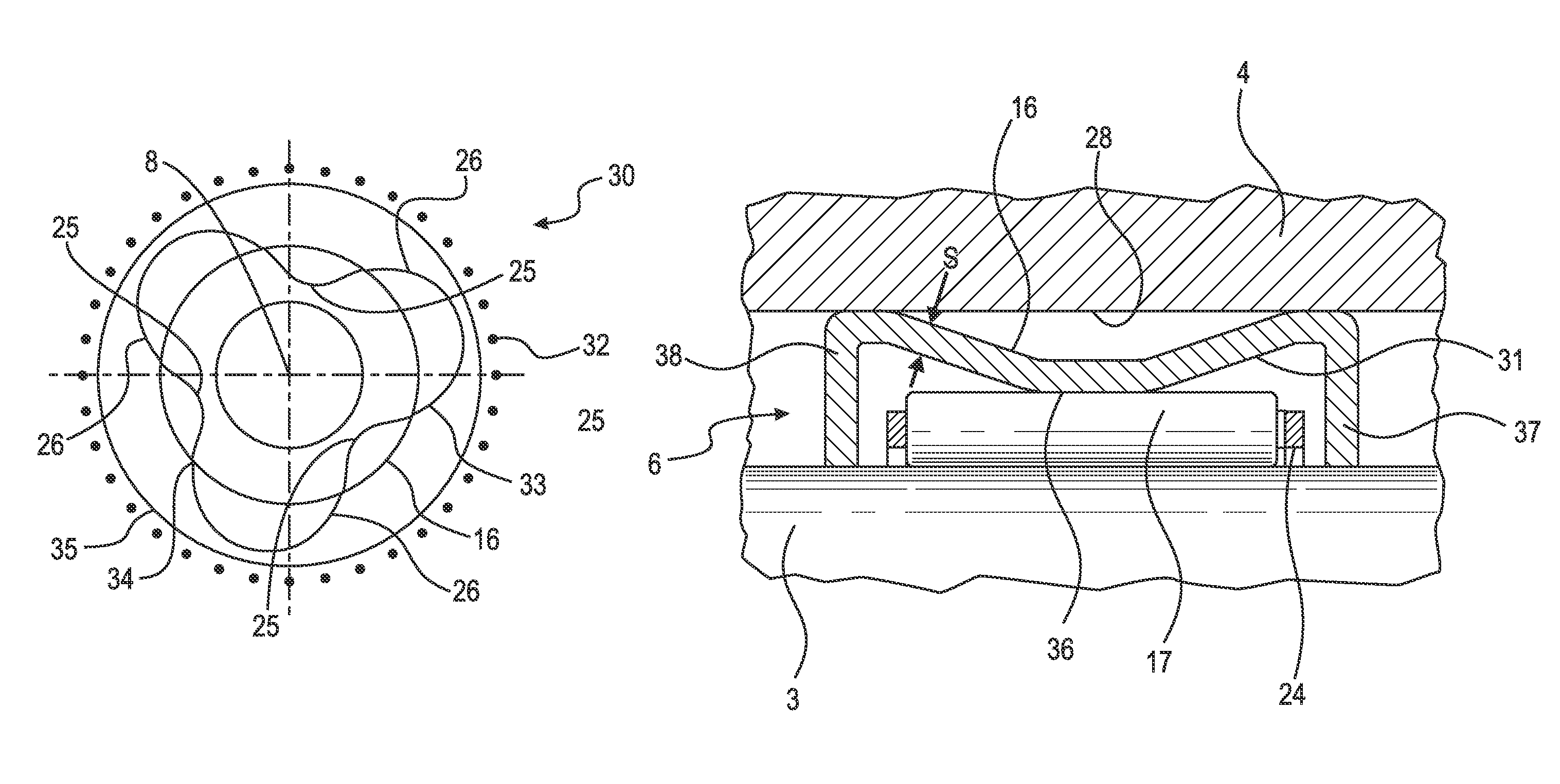
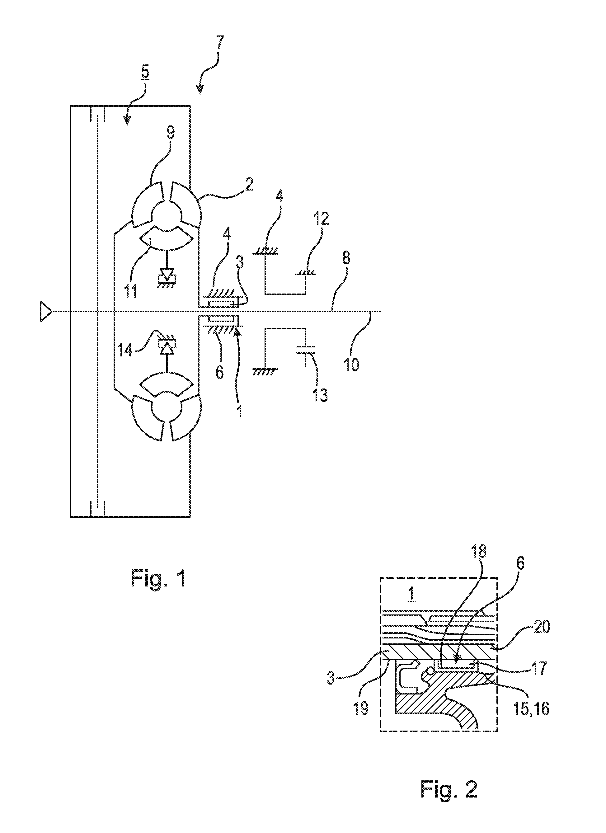
[0029]FIG. 1 shows in a highly simplified schematic form a transmission 7 with a bearing position 1 for rotatably mounting a pump impeller 2 on a housing 4. The pump impeller 2 of a torque converter 5 is connected to a converter neck 3. The converter neck 3 is mounted in the housing 4 by means of least one roller bearing 6 in such a way that said converter neck can rotate about the axis of rotation 8 of the pump impeller 2. The housing 4, is for example, a housing 4 of a primary pump (not shown in detail), by means of which the torque converter 5 and the transmission 7 are supplied with hydraulic fluid. The axis of rotation 8 of the pump impeller 2 is also the axis of rotation 8 of a turbine impeller 9, the axis of rotation of an input shaft 10 of the transmission and the axis of rotation of a stator impeller 11. The turbine impeller 9 of the torque converter 5 is connected to the transmission input shaft 10 of the transmission 7, which is connected to the torque converter 5. This i...


PUM

PropertyMeasurementUnit
diameteraaaaaaaaaa
diameteraaaaaaaaaa
full angleaaaaaaaaaa

Abstract

A bearing position for a torque converter, wherein a pump impeller is connected to a converter neck, and the pump impeller is rotatably mounted on the bearing position by at least one roller bearing in a housing, wherein the roller bearing comprises an outer rolling raceway, assigned to the converter neck and facing radially outwards, and an inner rolling raceway, assigned to the housing and facing radially inwards, and rollers disposed radially between the rolling raceways, wherein the bearing position comprises at least one radially elastically designed section of a sleeve of the roller bearing, where the sleeve is provided with the inner rolling raceway, wherein the section, enclosing an elastic convex raceway curvature, is resiliently prestressed in the radial direction against at least a first roller of the rollers, the first roller supported on the outer rolling raceway, and supported in the opposite radial direction on the housing.

Description

CROSS-REFERENCE TO RELATED APPLICATIONS[0001]This patent application is filed under 35 U.S.C. §111(a), 35 U.S.C. §120 and 35 U.S.C. §365(c) as a continuation of PCT Patent Application PCT / EP2013 / 058419, filed Apr. 24, 2013, and claims priority thereto, and claims priority to German Patent Application DE 102012207074.5, filed Apr. 27, 2012, and German Patent Application DE 102012222279.0, filed Dec. 5, 2012, which applications are hereby incorporated by reference in their entireties.FIELD OF THE INVENTION[0002]The invention relates to a bearing position for rotatably mounting a pump impeller of a torque converter in a housing, wherein the pump impeller is connected to a converter neck, by way of which the pump impeller is rotatably mounted on the bearing position by means of at least one roller bearing in the housing, wherein the rolling bearing comprises an outer rolling raceway, which is assigned to the converter neck and which faces radially outwards, and an inner rolling raceway,...

Claims


Application Information

Patent Timeline
Patent Type & Authority Patents(United States)
IPC IPC(8): F16C19/26F16C33/64F16C43/06F16C27/04F16C33/58F16C19/46
CPCF16C33/588F16C19/26F16C19/466F16C27/04F16C33/585F16C33/64F16C43/065F16C2360/00Y10T29/49686F16H41/24
Inventor PABST, ALEXANDERBEECK, FRANK
Owner SCHAEFFLER TECH AG & CO KG
Why Eureka
Try Eureka