Dual-shaft dual-mode continuously variable transmission

A technology of continuously variable transmission and torque converter, which is applied in the direction of vehicle gearboxes, transmission devices, fluid transmission devices, etc., and can solve the problems of increasing quality and cost, extending the axial length and lateral width of CVT, etc.

Inactive Publication Date: 2019-07-05
GM GLOBAL TECH OPERATIONS LLC
View PDF5 Cites 0 Cited by
  • Summary
  • Abstract
  • Description
  • Claims
  • Application Information

AI Technical Summary

Problems solved by technology

Each rotating shaft requires a separate set of bearing members, resulting in increased mass and cost, and the four-axis configuration extends the axial length and lateral width of the CVT

Method used


Image

  • Dual-shaft dual-mode continuously variable transmission
  • Dual-shaft dual-mode continuously variable transmission
  • Dual-shaft dual-mode continuously variable transmission

Examples


Embodiment Construction

[0025] The following description is merely exemplary in nature and is not intended to limit the invention, application or uses.

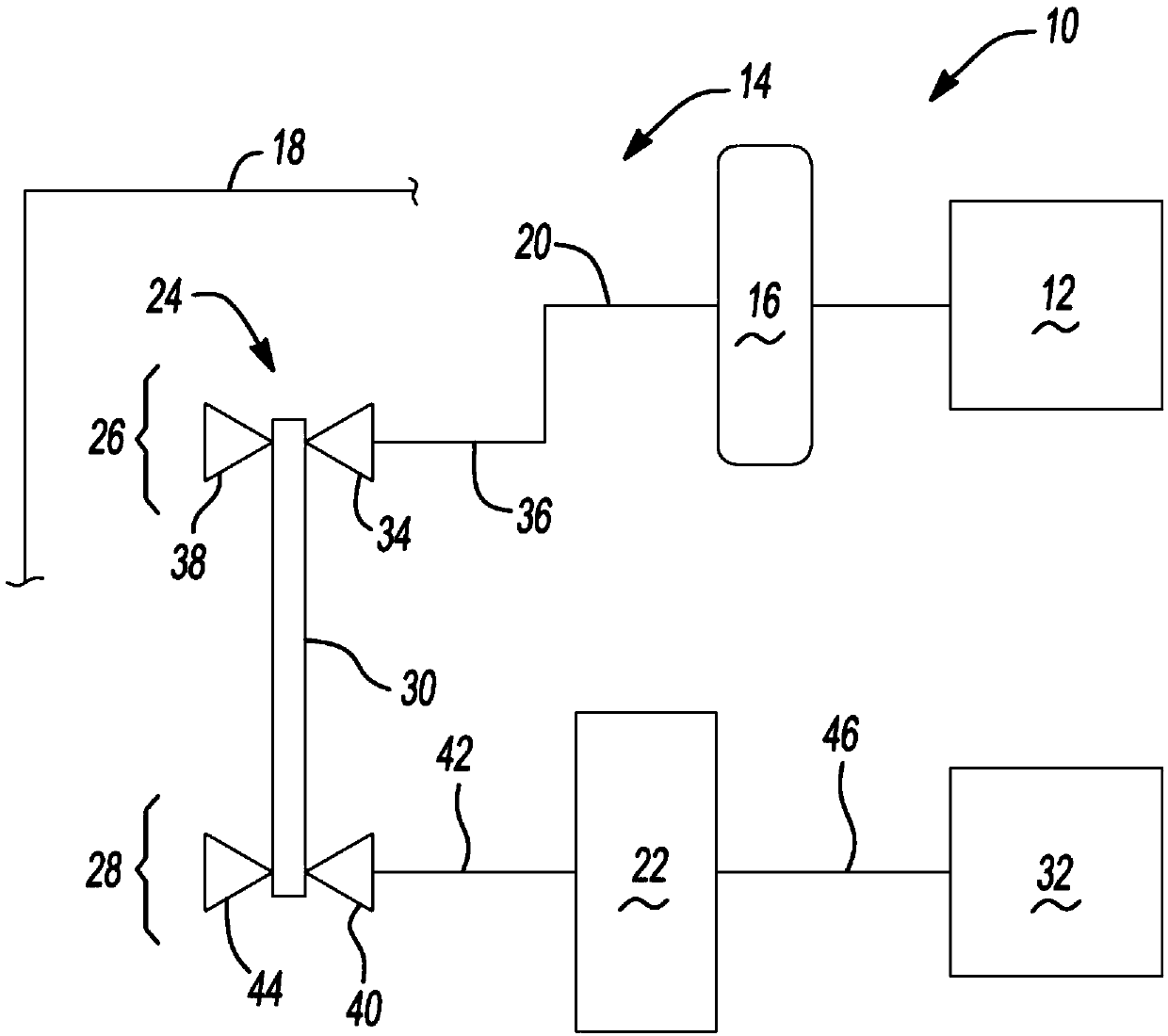
[0026] refer to figure 1 , a power train for a motor vehicle is indicated in its entirety by reference numeral 10 . The powertrain 10 includes an engine 12 (shown in block form) interconnected with a transmission 14 . Engine 12 may be a conventional gasoline, diesel or mixed fuel internal combustion engine, a hybrid engine, or an electric motor, or any other type of prime mover without departing from the scope of the present invention. The engine 12 provides drive torque to the transmission 14 through, for example, a torque converter 16 . It should be understood that other starting devices may be used, such as a launch clutch.

[0027] Transmission 14 is a variable diameter pulley or sheave driven continuously variable transmission (CVT). The CVT 14 includes a typically cast metal housing 18 that encloses and protects the various components of t...


PUM


Abstract

A continuously variable transmission (CVT) for a motor vehicle includes a transmission input shaft rotatably connected to an engine through a torque converter, the transmission input shaft defining a first CVT axis. A continuously variable transmission unit connected for rotation through a transmission input shaft includes a first pulley assembly, a second pulley assembly, and a flexible member wound around the first pulley assembly and the second pulley assembly. The dual mode transfer gear assembly is connected to the second pulley assembly and is coaxially aligned for rotation on the second CVT axis. A clutch assembly having at least one clutch is connected to the transfer gear assembly. A final drive unit connected to the transfer gear assembly is coaxially aligned with respect to the second CVT axis.

Description

technical field [0001] The present invention relates to automatic transmissions, and more particularly to a dual mode continuously variable transmission having assemblies disposed on two shafts. Background technique [0002] The statements in this section merely provide background information related to the present invention and may or may not constitute prior art. [0003] A continuously variable transmission ("CVT") typically includes a belt and pulley system that operably couples a source of rotating power, such as an engine or an electric motor, to a dual gear final drive unit. A belt and pulley system typically includes first and second pairs of pulley cones with a torque transmitting belt or chain extending between the cone pairs. Each pulley-cone pair includes an axially fixed pulley member and an axially movable pulley member. Each movable pulley member is axially adjustable relative to the fixed pulley member by a hydraulic system. A hydraulic system provides pri...

Claims


Application Information

Patent Timeline
Patent Type & Authority Patents(China)
IPC IPC(8): F16H47/08
CPCF16H37/022F16H3/663F16H37/0813F16H2037/023F16H2200/0034F16H2200/2005F16H2200/2023
Inventor J·M·哈特D·A·威尔顿
Owner GM GLOBAL TECH OPERATIONS LLC
Why Eureka
Try Eureka