Vertical take off aircraft

a vertical landing and aircraft technology, applied in vertical landing/take-off aircrafts, process and machine control, instruments, etc., can solve the problems of limiting the use of aircraft, limiting the fuel capacity and range of aircraft, and general limitation of aircraft types to lower air speeds

Active Publication Date: 2016-06-14
MARTIN UAV
View PDF4 Cites 14 Cited by
  • Summary
  • Abstract
  • Description
  • Claims
  • Application Information

AI Technical Summary

Benefits of technology

[0005]In an embodiment, an aircraft includes a fuselage, a wing, a ducted fan, a propulsion unit, and a controller. The fuselage has a nose end and a second, opposing end defined as a tail end. The wing coupled to the fuselage between the nose end and the tail end. The ducted fan is coupled to the fuselage at a point between a location where the wing is coupled to the fuselage and the tail end of the fuselage. The propulsion unit is coupled to the ducted fan and is operable with the ducted fan to generate a thrust at least equal to a weight of the aircraft. The controller is operable to control the aircraft in (1) a vertical flight mode in which a first lifting force generated by the ducted fan is greater than a second lifting force generated by the wing, (2) a horizontal flight mode in which the second lifting force is greater than the first lifting force, and (3) transition the aircraft from the vertical flight mode to the horizontal flight mode.
[0006]In an embodiment, an aircraft includes a ducted fan, a fuselage, a wing, and a controller. The ducted fan has a plurality of controllable vanes. The fuselage is dispose...

Problems solved by technology

However, because air needs to pass over the wing to generate the lift force, the aircraft must be accelerated on the ground until sufficient lift can be generated for take off.
This limits the use of the aircraft to locations where there are suitable and accessible areas to accommodate take off and landing procedure.
However, significantly more power is required to generate a lifting force thereby limiting the fuel capacity and range of the aircraf...

Method used


Image

  • Vertical take off aircraft
  • Vertical take off aircraft
  • Vertical take off aircraft

Examples


Embodiment Construction

[0027]Various aspects of an aircraft according to the present disclosure are described. It is to be understood, however, that the following explanation is merely exemplary in describing the devices and methods of the present disclosure. Accordingly, any number of reasonable and foreseeable modifications, changes, and / or substitutions are contemplated without departing from the spirit and scope of the present disclosure.

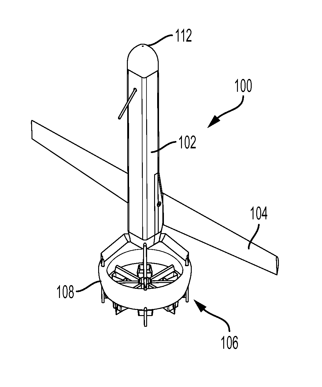
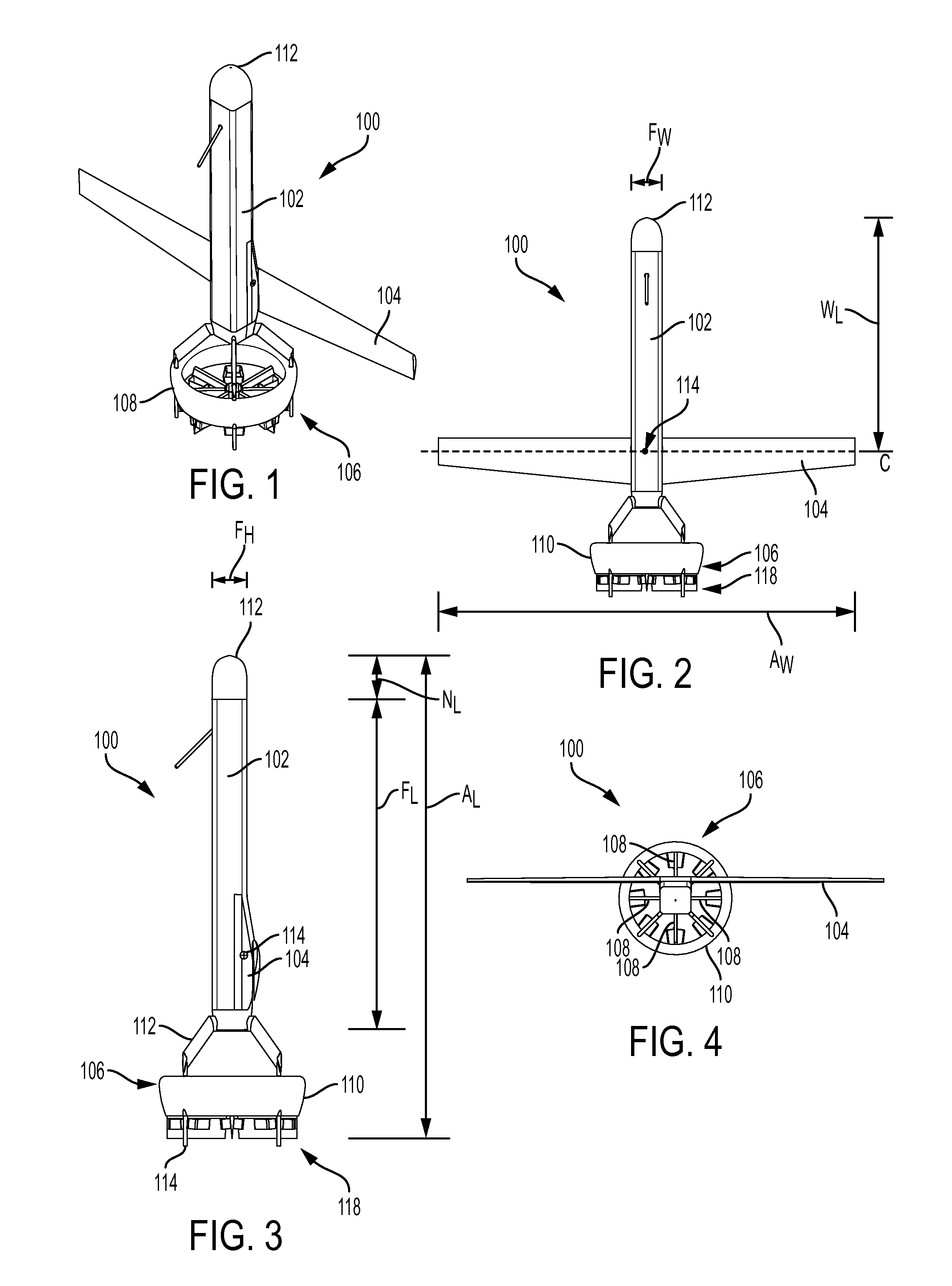
[0028]Referring to FIGS. 1-4, an aircraft 100 includes a fuselage 102, a wing 104, and a ducted fan lift system 106 with integral control vanes 108. The ducted fan lift system 106 may include: a duct 110 that is coupled to the fuselage 102 by struts 112, and ground contact protrusions 114 extending from the duct 110. The ducted fan system 106 provides enough thrust at zero velocity to allow the aircraft to hover, preferably 25% more thrust than the maximum vehicle weight.

[0029]The duct 110 is located at a distance below the wing 104 (i.e., the wing 104 is disposed bet...


PUM


Abstract

An aircraft includes a fuselage, a wing, a ducted fan and a controller. The wing and the ducted fan are coupled to the fuselage. The controller is operable to control the aircraft in a vertical flight mode, a horizontal flight more, and transition the aircraft from the vertical flight mode to the horizontal flight mode.

Description

BACKGROUND[0001]Aircraft are generally considered to be one of two different types based on how they generate lift. A first type generates lift force from air passing over a fixed wing. This type of aircraft generally has a good lifting capacity, which also means that it can carry large amounts of fuel for sustained flight. However, because air needs to pass over the wing to generate the lift force, the aircraft must be accelerated on the ground until sufficient lift can be generated for take off. This limits the use of the aircraft to locations where there are suitable and accessible areas to accommodate take off and landing procedure.[0002]A second type of air craft generates lift force from a rotating blade. Because the blade itself rotates, a lift force can be generated while the aircraft is stationary on the ground enabling it to be deployed from locations that cannot accommodate take off and landing of a fixed wing aircraft. However, significantly more power is required to gen...

Claims


Application Information

Patent Timeline
IPC IPC(8): B64C29/00B64C29/02B64C11/00G05D1/08G05D1/10
CPCB64C29/02B64C11/001G05D1/0858G05D1/102B64C2009/005B64U70/80B64U10/25B64U50/14B64U50/13B64U20/70B64C39/024
Inventor MORRIS, STEPHEN
Owner MARTIN UAV
Why Eureka
Try Eureka