Circuits and methods for impedance calibration

a technology of impedance calibration and circuit, applied in the field of electronic circuits, can solve problems such as loss of transmitted data

Active Publication Date: 2016-06-14
TAHOE RES LTD
View PDF17 Cites 16 Cited by
  • Summary
  • Abstract
  • Description
  • Claims
  • Application Information

AI Technical Summary

Problems solved by technology

The signal reflections may corrupt the transmitted signal received by the receiver, causing loss of the transmitted data.

Method used


Image

  • Circuits and methods for impedance calibration
  • Circuits and methods for impedance calibration
  • Circuits and methods for impedance calibration

Examples


Embodiment Construction

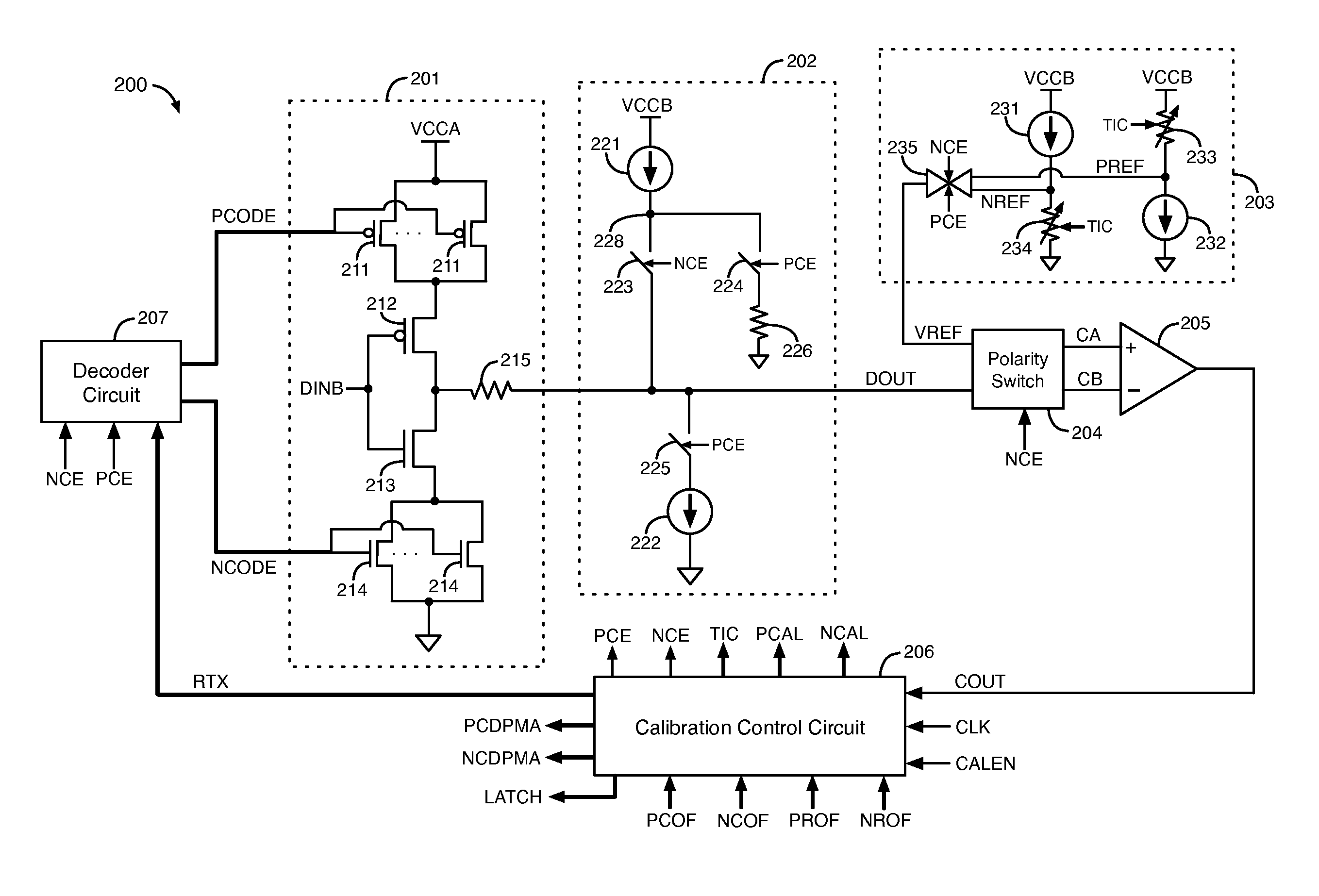
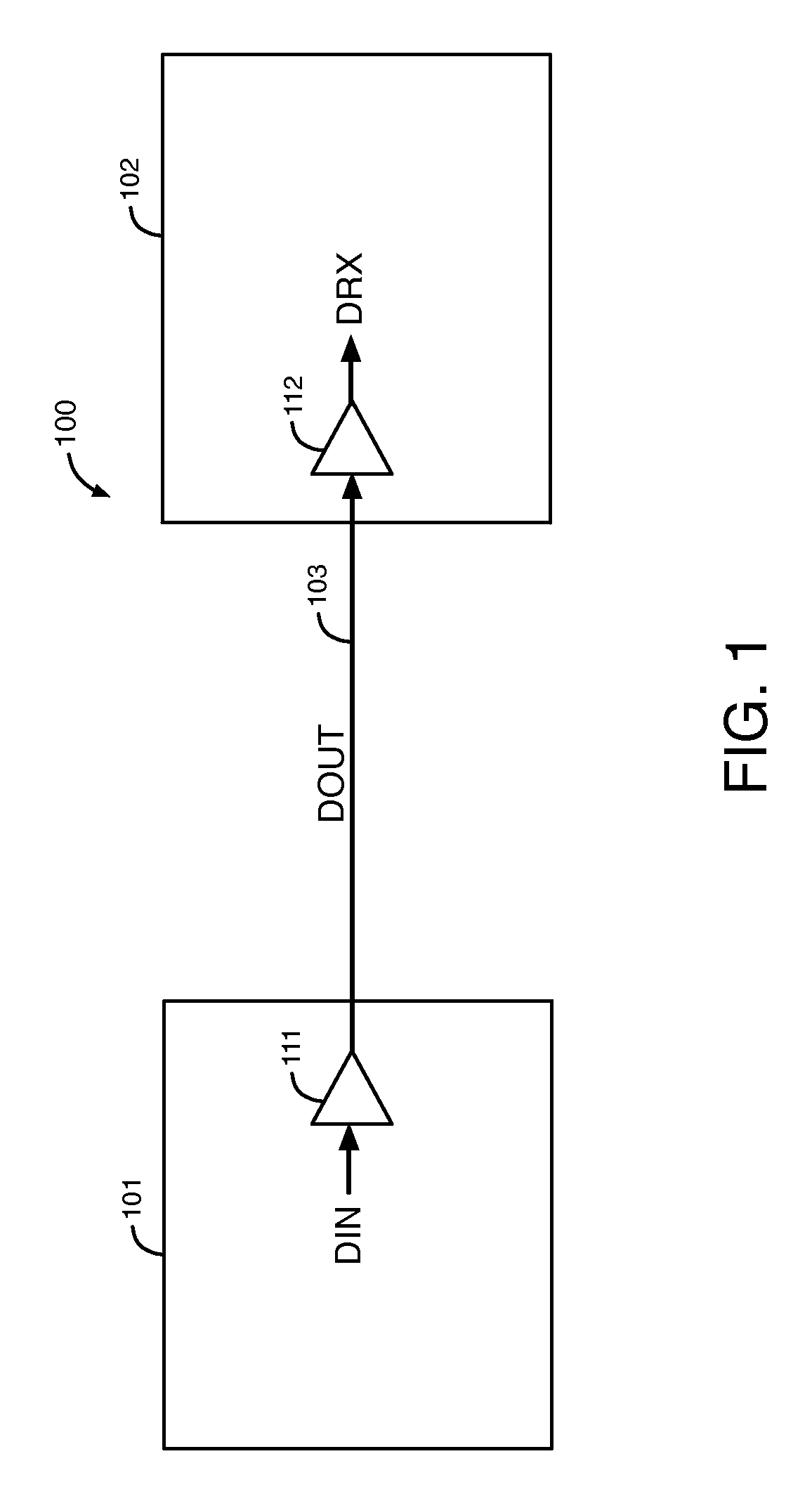
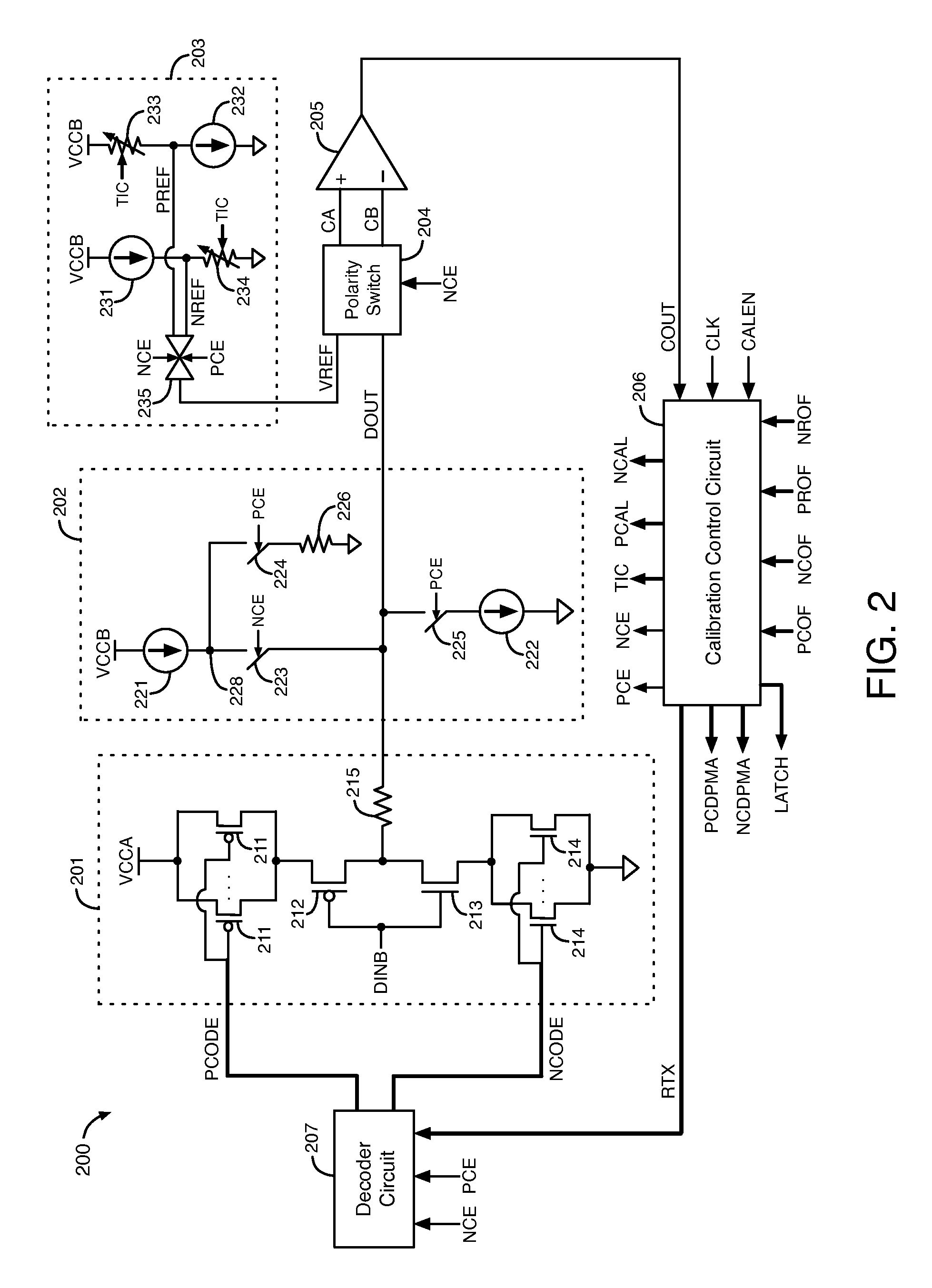
[0014]The output resistance of a driver circuit in a transmitter is selected to match the characteristic impedance of the transmission link coupled to the output of the driver circuit in order to reduce or eliminate signal reflections in the transmission link. If the output resistance of the driver circuit does not match the characteristic impedance of the transmission link, a reflected signal wave may be generated in the transmission link that causes loss in a signal transmitted by the driver circuit through the transmission link. It is therefore desirable to reduce or avoid mismatch between the output resistance of a driver circuit in a transmitter and the characteristic impedance of a transmission link in order to preserve the integrity of a signal that the driver circuit transmits through the transmission link.

[0015]The output resistance of a driver circuit in a transmitter may be adjusted for a variety of reasons. For example, different data transmission protocols may use trans...


PUM


Abstract

A driver circuit drives data to an output based on an input data signal in a transmission mode. The driver circuit includes transistors. A comparator generates a comparison output in a calibration mode based on a reference signal and a signal at the output of the driver circuit. A calibration control circuit adjusts an equivalent resistance of the transistors in the driver circuit based on the comparison output in the calibration mode. The equivalent resistance of the transistors in the driver circuit can be adjusted to support the transmission of data according to multiple different data transmission protocols using transmission links having different characteristic impedances. The equivalent resistance of the transistors in the driver circuit can also be adjusted to compensate for resistance in the package routing conductors and / or to compensate for parasitic resistance.

Description

FIELD OF THE DISCLOSURE[0001]The present disclosure relates to electronic circuits, and more particularly, to circuits and methods for impedance calibration.BACKGROUND[0002]In a data transmission system, one or more signals are transmitted from a transmitter to a receiver through external transmission links. If the bit period of a transmitted signal is shorter than the transmission time of the transmitted signal, as in high speed transmission links, reflections of the transmitted signal may arrive at the receiver with the main transmitted signal. The signal reflections may corrupt the transmitted signal received by the receiver, causing loss of the transmitted data.BRIEF SUMMARY[0003]According to some embodiments, a driver circuit drives data to an output based on an input data signal in a transmission mode. The driver circuit includes transistors. A comparator generates a comparison output in a calibration mode based on a reference signal and a signal at the output of the driver ci...

Claims


Application Information

Patent Timeline
Patent Type & Authority Patents(United States)
IPC IPC(8): H03K19/16H03K19/00H04L25/02
CPCH03K19/0005H04L25/028H04L25/0278G11C29/022G11C29/028H03K19/17724H03H11/28H03K17/687
Inventor TAN, KOK SIANGHOANG, TIM TRI
Owner TAHOE RES LTD
Why Eureka
Try Eureka