
Flue gas-treating method and apparatus for treating acidic tail gas by using ammonia process

a technology of ammonia and tail gas, applied in the direction of chemistry apparatus and processes, separation processes, dispersed particle separation, etc., can solve the problems of high operating cost, high investment, complex process, etc., and achieve low investment, full utilization, and high efficiency

Active Publication Date: 2016-06-21
JIANGNAN ENVIRONMENTAL PROTECTION GRP INC
View PDF131 Cites 42 Cited by
  • Summary
  • Abstract
  • Description
  • Claims
  • Application Information

AI Technical Summary

Benefits of technology

[0009]The purpose of this invention is to provide a method for treating acid tail gas by using an ammonia process and an apparatus thereof. Especially the combination of the Claus process and the ammonia desulfurization technology can effectively improve the acid tail gas desulfurization efficiency, and effectively control the ammonia slip and the aerosol generation. In addition, this process is simple and operating cost is low. The desulfurization efficiency is ≧95%, and the ammonia recovery ratio is ≧96.5%.
[0015]4) providing an absorption section in the absorber wherein the absorption section achieves desulfurization spray absorption by using absorption solution distributors via an absorption solution containing ammonia. This setting ensures the desulfurization efficiency to be over 95%.
[0016]5) providing a water washing layer above the absorption section in the absorber, wherein the water washing layer washes the absorption solution droplets in the tail gas to reduce the slip of the absorption solution as well as to control the water washing flow in order to keep the concentration of the absorption solution.
[0017]6) providing a demister above the water washing layer inside the absorber to control the mist droplets concentration in the cleaned tail gas.
[0038]This invention provides a process scheme of desulfurizing acid tail gas with high efficiency, low investment and full utilization. The integrated design combining the byproduct generated from acid gas ammonia desulfurization unit with the boiler ammonia desulfurization units can reduce investment of the post-treatment system and simplifies the process flow. This method intensifies the environmental control for plants, and benefits the operation management.
[0039]Spray cooling with process water and / or the ammonium sulfate solution is set in the inlet duct of the absorber or inside the absorber to cool the acid tail gas entering the absorber to below 125° C., and also to save energy consumed in the evaporation crystallization of ammonium sulfate. In addition, supplying air to achieve a proper acid tail gas concentration broadens the industrial applications of ammonia desulfurization process. For example, in coal chemical industry, if the Claus sulfur recovery process is combined with the ammonia desulfurization technology, over 99.5% desulfurization efficiency and about 95% sulfur recovery efficiency can be achieved. The byproduct ammonium sulfate can be sold directly, there is no secondary pollution, the process is simple and easy to operate, and the capital and operating costs are low. The technology does not require complicated control in the Claus sulfur recovery process or other refined Claus processes. Sulfur that cannot be recovered in the Claus process can be recovered by the method described in this invention, which effectively improves the desulfurization efficiency and controls ammonia slip and aerosol generation. In addition, this process is simple and the operating cost is low. This invention, with excellent performance in terms of desulfurization efficiency and ammonia recovery, provides a novel solution for air pollution control problems such as the haze which happened frequently in China recently. The byproducts of the ammonia desulfurization can be used effectively, making this process more economically viable. The design of the devices in this invention is also simple and reliable. The combination of a cooling spray layer and an absorption spray layer a, as well as a blower with adjustable flow rate make it more convenient to treat acid tail gas in time.

Problems solved by technology

Sulfur dioxide discharged from industrial processes is the major source of acid rain and sulfur dioxide pollution.
All these processes have the disadvantages of complicated process, high investment, high operating cost, difficult operation or the like.
Such control is complicated, and if stable control cannot be achieved, the sulfur recovery efficiency will be greatly affected.
This method also has the disadvantages of high capital and operating costs, and complicated operation or the like.
Capital and operating costs for limestone desulfurization device are high, and especially, it requires high-quality limestone, and the market for the desulfurization byproduct (gypsum) is limited.
Sodium carbonate and sodium hydroxide desulfurization, which is often used in acid tail gas desulfurization treatment, consumes sodium carbonate and sodium hydroxide, and the market for its byproduct sodium sulfate is limited, resulting in high operating cost and poor reliability.

Method used


Image

  • Flue gas-treating method and apparatus for treating acidic tail gas by using ammonia process
  • Flue gas-treating method and apparatus for treating acidic tail gas by using ammonia process
  • Flue gas-treating method and apparatus for treating acidic tail gas by using ammonia process

Examples


example 1

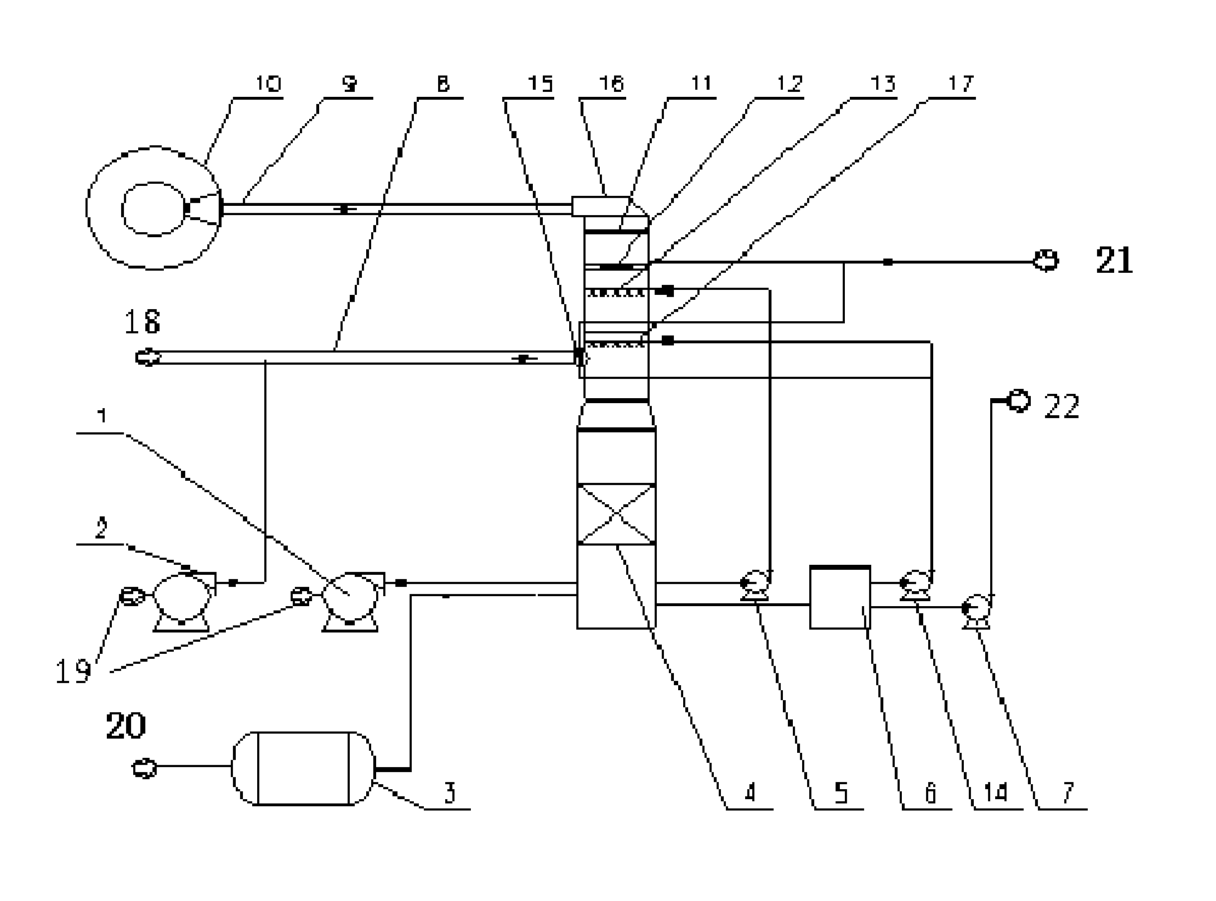
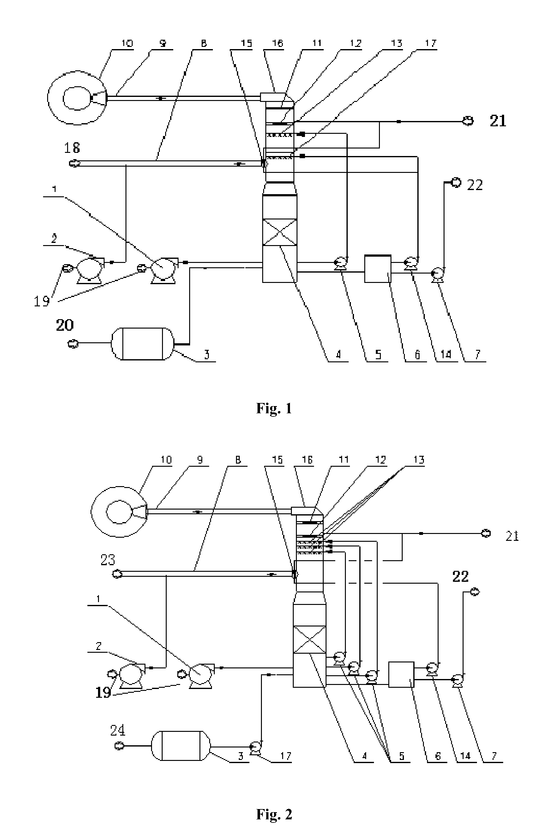
FIG. 2 Shows an Ammonia Desulfurization Apparatus for Treating Acid Tail Gas from a Natural Gas Plant

[0075]The total flow rate of acid tail gas is 13,375 Nm3 / h, the temperature is 152° C., the concentration of sulfur dioxide in the acid tail gas is 31,443 mg / Nm3, and the pressure is 100,000 Pa. The absorbent is aqueous ammonia with a concentration of 15%.

[0076]Process flow and devices: FIG. 2 shows the process flow diagram and devices. After the acid tail gas is supplemented with ambient-temperature air by the air blower 2, the concentration of sulfur dioxide is decreased to 22,000 mg / Nm3 and the temperature is decreased to 115° C. The temperature of acid tail gas is further decreased to 70° C. at inlet of the absorber by being cooled with process water and ammonium sulfate solution spray layer 15 (process water flow rate is 0.2 m3 / h and ammonium sulfate solution flow rate is 20 m3 / h). Then the flue gas enters the absorber 16 to be sprayed with absorption solution. Then the process ...

example 2

The Ammonia Desulfurization Apparatus for Treating Tail Gas from the Claus Sulfur Recovery Process from a Coal Chemical Plant

[0088]Acid tail gas from the Claus sulfur recovery unit of a coal chemical plant is generated from acid gas after going through a two-stage Claus sulfur recovery process, a tail gas incinerator and a waste heat boiler. The total flow rate of acid tail gas is 59,912 Nm3 / h, the temperature is 165° C., the concentration of sulfur dioxide in the acid tail gas is 12,600 mg / Nm3, and the oxygen concentration is 2% and the pressure is 0.02 MPa. The absorbent is 99.6% anhydrous ammonia.

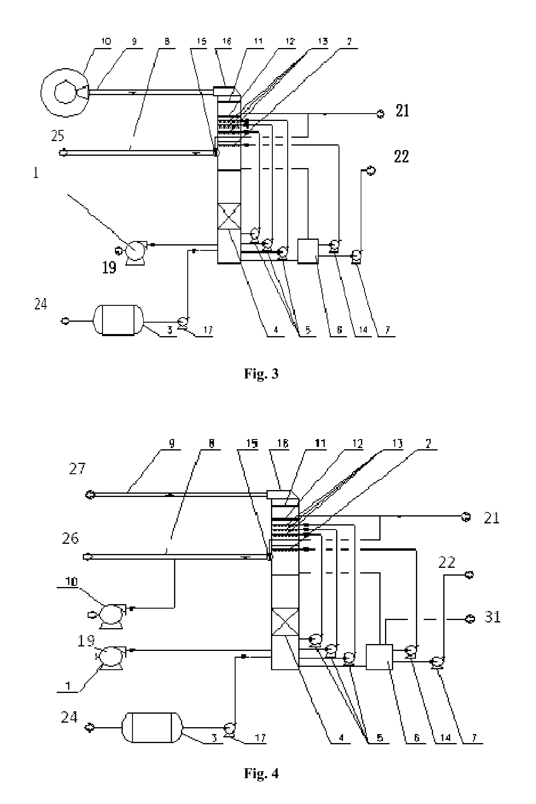
[0089]Process Flow: FIG. 3 shows the process flow chart. The acid tail gas flows into the absorber 16 after being cleaned and cooled to around 100° C. by process water (1 m3 / h) spray layer 15 at the inlet of the absorber, and then the gas is cleaned by the washing and cooling spray layer 2 (ammonium sulfate solution, 120 m3 / h) inside the absorber. After the process gas is cooled to about...

example 3

Ammonia Desulfurization Devices for Treating Acid Tail Gas from a Chemical Project

[0105]Acid gas with sulfur and organic waste liquid generated from a chemical project is burned inside a incinerator, and the heat is recycled by a waste heat boiler to produce the byproduct steam, and then generates acid tail gas with sulfur dioxide. The total acid tail gas flow rate is 11,018 Nm3 / h, the temperature is 350° C., the concentration of sulfur dioxide is 2.57% (v%), that the concentration of oxygen is 6.22%, and the the pressure is 5,000 Pa.

[0106]The absorbent is 99.6% anhydrous ammonia.

[0107]Process Flow: FIG. 4 shows the process flow chart. The concentration of sulfur dioxide in acid tail gas is reduced to 6680 mg / Nm3 after the supplement of ambient-temperature air from the air blower 10, and then the temperature is decreased to 60° C. The acid tail gas is cleaned and cooled by spraying process water (0.5 m3 / h) in the spray layer 15 at inlet of the absorber, and then the process gas goes...


PUM

PropertyMeasurementUnit
temperatureaaaaaaaaaa
operating temperatureaaaaaaaaaa
pressureaaaaaaaaaa

Abstract

A flue gas-treating method for treating acid tail gas by using an ammonia process, comprising the following steps of: 1) controlling the concentration of sulfur dioxide in an acid tail gas entering an absorber to be ≦30,000 mg / Nm3; 2) spraying and cooling with a process water or / and an ammonium sulfate solution in the inlet duct of the absorber or inside the absorber; 3) providing an oxidation section in the absorber, wherein the oxidation section is provided with oxidation distributors for oxidizing the desulfurization absorption solution; 4) providing an absorption section in the absorber wherein the absorption section achieves desulfurization spray absorption by using absorption solution distributors via an absorption solution containing ammonia; the absorption solution containing ammonia is supplied by an ammonia storage tank; 5) providing a water washing layer above the absorption section in the absorber, wherein the water washing layer washes the absorption solution in the tail gas to reduce the slip of the absorption solution; 6) providing a demister above the water washing layer inside the absorber to control the concentration of mist droplets contained in the cleaned tail gas. In the coal chemical industry, the integration of the Claus sulfur recovery process and the ammonia desulfurization technology can reduce the investment of the post-treatment and simplify the operation process, and provide intensive advantages to the environmental control of plants.

Description

CROSS REFERENCE TO RELATED APPLICATIONS[0001]This application is a continuation of U.S. patent application Ser. No. 14 / 409,781 filed Dec. 19, 2014, which is a National Stage Entry of International Application No. PCT / CN2013 / 074657 filed Apr. 24, 2013, the entire contents of which are incorporated herein by reference herein.FIELD OF THE INVENTION[0002]This invention relates to a purification technology and an apparatus for industrial flue gas such as an acid tail gas (flue gas) or the like in chemical (coal chemical) process. Specifically, the invention relates to a desulfurization technology and an apparatus using ammonia as the absorbent to remove sulfur dioxide from a flue gas and yield a fertilizer as a byproduct. This invention belongs to the technical fields of environmental protection, power and chemical industry or the like.BACKGROUND OF THE INVENTION[0003]Sulfur dioxide discharged from industrial processes is the major source of acid rain and sulfur dioxide pollution. In ord...

Claims


Application Information

Patent Timeline
Patent Type & Authority Patents(United States)
IPC IPC(8): B01D53/50B01D53/78
CPCB01D53/502B01D53/504B01D53/78B01D2251/2062B01D2251/11B01D2252/102B01D2252/103B01D2257/302B01D2257/406B01D2258/0283
Inventor XU, CHANGXIANGLUO, JINGFU, GUOGUANGXU, YANZHONG
Owner JIANGNAN ENVIRONMENTAL PROTECTION GRP INC
Learn More