Linear electro-mechanical actuator with built-in anti-rotation

an electromechanical actuator and built-in technology, applied in the direction of toothed gearings, belts/chains/gearings, toothed gearings, etc., can solve the problems of low system reliability, rapid deterioration of performance, and increase of translatory masses, and achieve high robustness

Active Publication Date: 2016-06-21
UMBRAGRP SPA
View PDF18 Cites 6 Cited by
  • Summary
  • Abstract
  • Description
  • Claims
  • Application Information

AI Technical Summary

Benefits of technology

[0012]More specifically, the aim of this invention is to provide a linear electro-mechanical actuator with built-in anti-rotation which has high robustness and, at the same time, compact dimensions.

Problems solved by technology

The traditional anti-rotation systems have the following limitations:they are highly susceptible to misalignment between the actuator and the structure where the anti-rotation is performed; in particular, in all those applications with high operational loads and continuous operating conditions, the misalignments between actuator and anti-rotation structure generate transversal loads on the actuator which can lead to a malfunction of the device, a rapid deterioration of its performance and, therefore, a low reliability of the system;all those applications with high operational loads and continuous operating conditions require large spaces for containing an anti-rotation structure which is sufficiently robust to satisfy the load capacity and duration requirements needed by the application;they lead to an increase in the translatory masses of the actuator and, therefore, to a reduction in the dynamic performance of the system;the anti-rotation systems of the sliding type are traditionally used where the pressures between the contact elements and the duration requirements are substantially reduced; in applications with high operational loads and continuous operating conditions, the sliding type anti-rotations systems can lead to a rapid deterioration of the performance and, therefore, to a low reliability of the system.the anti-rotations systems are normally positioned in series relative to the recirculating ball screw element leading to a large axial dimension and, in any case, to the sum in series of the stroke of the screw with the stroke of the anti-rotation.

Method used


Image

  • Linear electro-mechanical actuator with built-in anti-rotation
  • Linear electro-mechanical actuator with built-in anti-rotation
  • Linear electro-mechanical actuator with built-in anti-rotation

Examples


Embodiment Construction

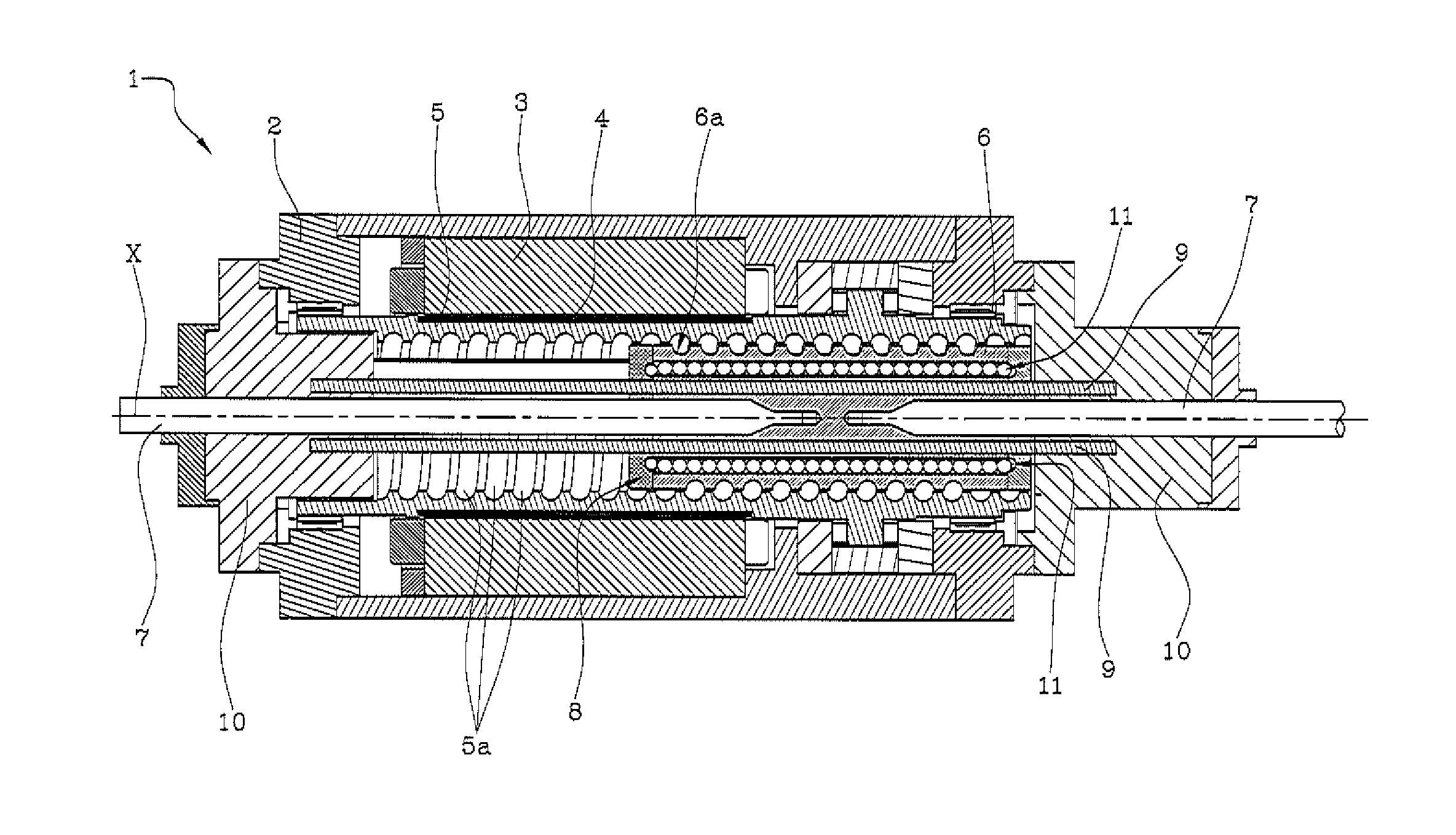
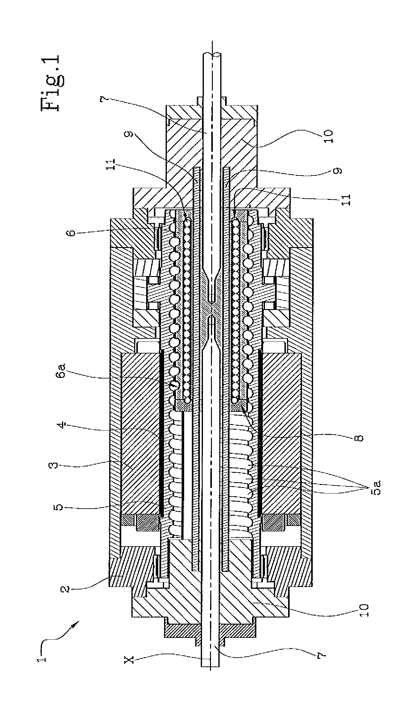
[0022]With reference to the accompanying drawings, the numeral 1 denotes in its entirety a linear electro-mechanical actuator with built-in anti-rotation.

[0023]As shown in FIG. 1, the actuator 1 comprises a rigid containment structure 2 housing an electric motor, in particular an outer stator 3 and a rotor 4 positioned inside the stator 3.

[0024]Inside the rotor 4, and in rigid connection with it, there is a nut 5 having an axis of rotation “X” which coincides with the axis of the rotor 4. The nut 5 if therefore rotated by the electromagnetic interaction between rotor 4 (usually of the permanent magnets type) and stator 5.

[0025]In the embodiment illustrated, the nut 5 has a main direction of extension coinciding with the above-mentioned axis “X”.

[0026]The nut 5 is only enabled for rotating about the axis “X”, and is prevented from translating along the axis “X” for example by special locking shoulders or other known solutions.

[0027]Inside the nut 5 there is a screw shaft 6 which exte...


PUM


Abstract

A linear electro-mechanical actuator, includes a containment structure (2), one or two pushers facing each other (7), a nut (5) rotatable about an axis (X) driven by a driving force, a screw shaft (6) inserted in the nut (5), connected to the pushers and interconnected with the nut (5) via a helical recirculating ball coupling (5a, 6a), and an anti-rotation mechanism (8) acting on the screw shaft (6) to prevent the screw shaft (6) from rotating about the axis (X). The anti-rotation mechanism (8) includes a pair of fixed guide bars (9), coupled in a sliding fashion with the screw shaft (6) and extending along a direction parallel to the axis (X) and spaced from the axis (X).

Description

TECHNICAL FIELD[0001]This invention relates to a linear electro-mechanical actuator with built-in anti-rotation, in particular of the recirculating ball screw type.[0002]The linear electro-mechanical actuators generally have an electric motor the stator of which is connected to a screw device (for example of the recirculating ball screw type) designed to transform the rotary movement of the rotor into a linear forward movement of one or more pushers forming part of the screw device.[0003]So that the above-mentioned pushers (translatory elements of the screw device) can be provided with only linear translating motion, the linear electro-mechanical actuator must be equipped with an anti-rotation system which, for the equilibrium of the forces, balances the torque generated by the electric motor.BACKGROUND ART[0004]Prior art anti-rotation systems are described, for example, in the patent publications JP2002-54708 and JP59-19762 and use anti-rotation structures forming part of the actua...

Claims


Application Information

Patent Timeline
Patent Type & Authority Patents(United States)
IPC IPC(8): F16H3/06F16H25/24F16H25/22F16H25/20
CPCF16H25/24F16H25/2214F16H2025/204F16H2025/2078Y10T74/18576
Inventor PIZZONI, LUCIANOBEFFA, ROMANOMACCAGLIA, RICCARDOBOSI, MASSIMILIANOPIERMARINI, MARCELLO
Owner UMBRAGRP SPA
Why Eureka
Try Eureka