Modular patient handling system for medical imaging apparatus

a patient handling and medical imaging technology, applied in the field of medical diagnostic imaging system patient handling system, can solve the problems of patient discomfort, complex and time-consuming process of precision array of holes and subsequent threaded rod embedding, image distortion during diagnostic scanning procedures, etc., and achieve the effect of affecting image quality and reducing patient weight load

Active Publication Date: 2016-06-28
SIEMENS MEDICAL SOLUTIONS USA INC
View PDF8 Cites 0 Cited by
  • Summary
  • Abstract
  • Description
  • Claims
  • Application Information

AI Technical Summary

Benefits of technology

[0015]Accordingly, an object of the invention is to create a medical diagnostic imaging apparatus patient table that is capable of supporting a larger patient weight load without causing excessive load deflection within or external the patient bore that can adversely impact image quality.
[0016]Another object of the invention is to create a medical diagnostic imaging apparatus patient table that is capable of supporting a larger patient weight load without increasing component size within the imaging field of view that can adversely impact image quality.
[0017]An additional object of the invention is to create a medical diagnostic imaging apparatus patient table that increases available patient imaging volume within a given size imaging system patient bore.

Problems solved by technology

Creation of a precision array of holes and subsequent threaded rod embedding is complex and time consuming.
Excessive weight deflection loads can cause unwanted vertical movements (often referred to as “porpoiseing”) that can cause image distortion during diagnostic scanning procedures.
Patient transfers to the imaging system 10′ patient bed 50′—whether ambulatory or non-ambulatory—can cause patient discomfort and are relatively laborious for assisting medical personnel.
External columns require the aforementioned construction costs and efforts necessary for affixing them to the imaging room floor.
The external columns also have the aforementioned problems of consuming floor space and inhibiting maneuvering of patient transport beds proximal to the imaging apparatus.

Method used


Image

  • Modular patient handling system for medical imaging apparatus
  • Modular patient handling system for medical imaging apparatus
  • Modular patient handling system for medical imaging apparatus

Examples


Embodiment Construction

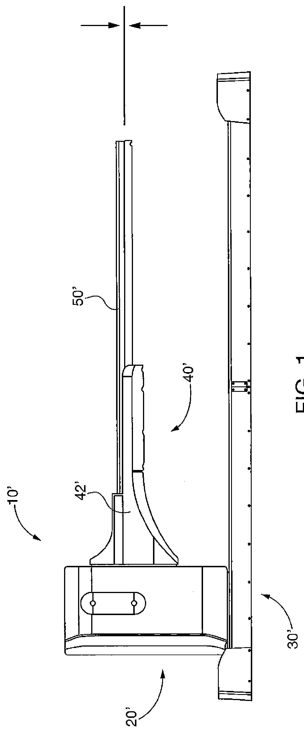
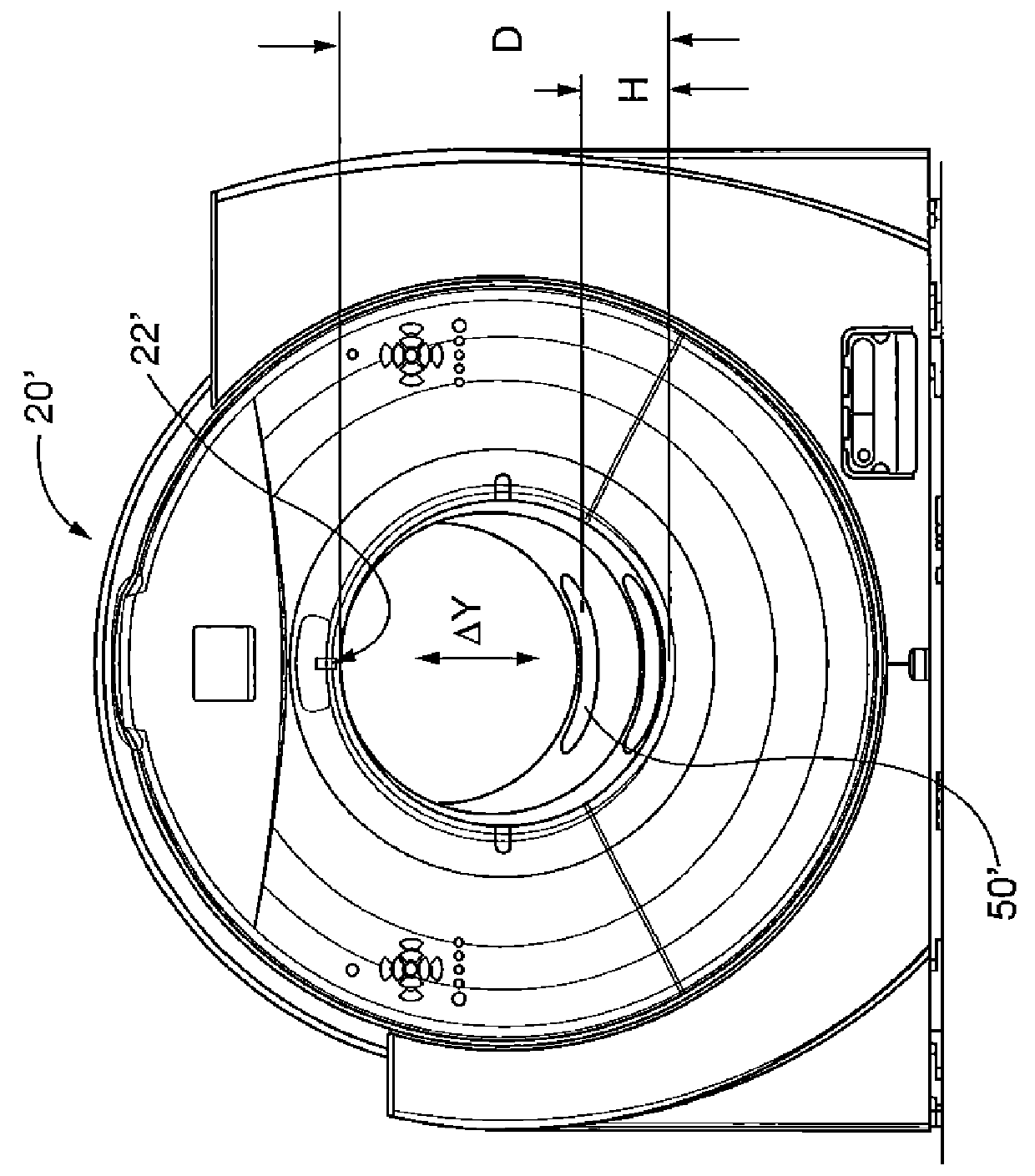
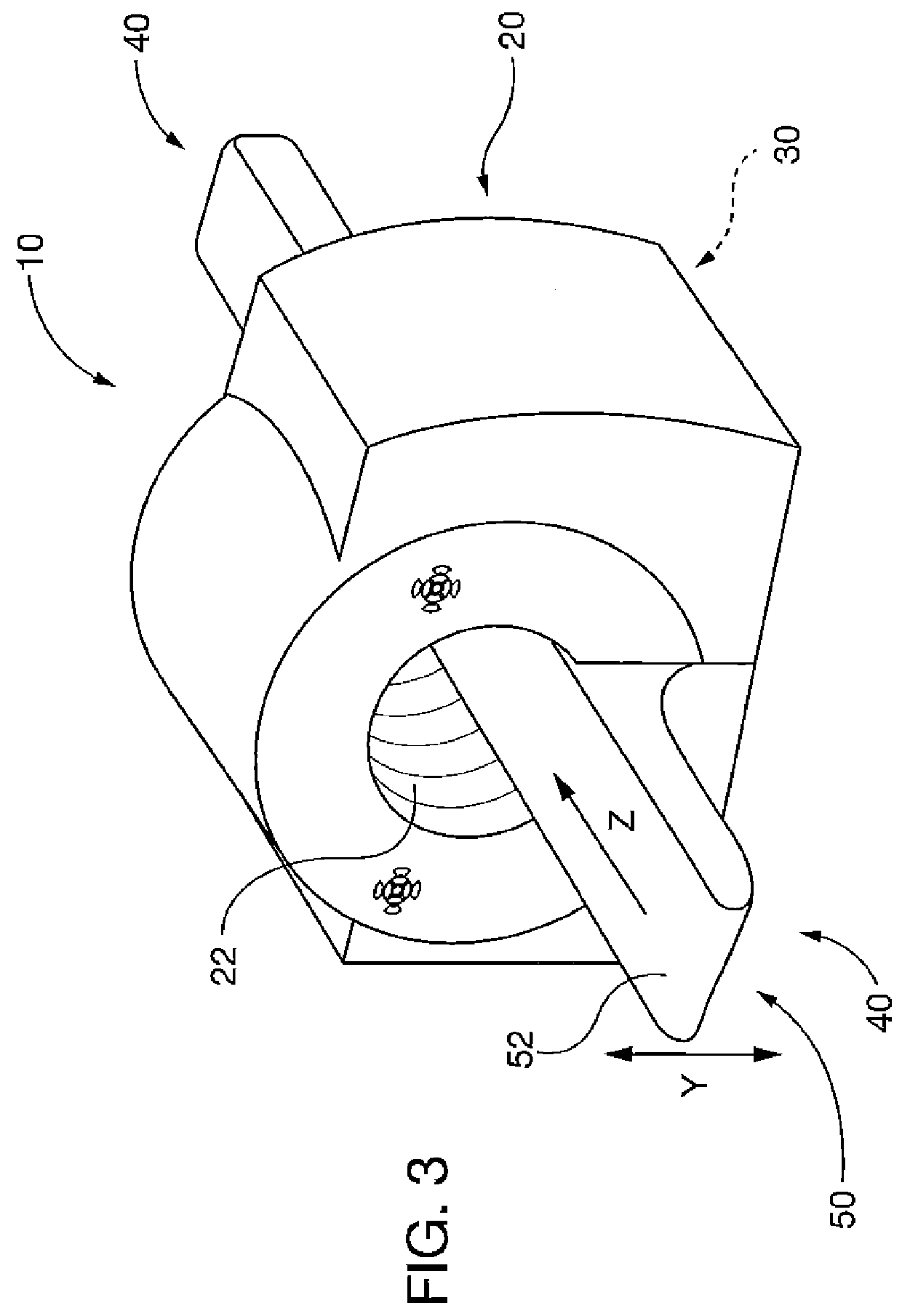
[0035]After considering the following description, those skilled in the art will clearly realize that the teachings of the present invention can be readily utilized in a modular patient handling system for medical imaging apparatus that includes a patient table, which mounts to a an existing patient imaging apparatus support base. When attached to first and second support ends of an imaging apparatus, the patient table has a generally planar patient support adapted for spanning the imaging apparatus field of view (FOV), and is analogous to a beam spanning the FOV. The beam-like patient support has sufficient rigidity for supporting and imaging a patient placed thereupon without any additional external support columns affixed to the imaging room floor, as were used in previously existing imaging apparatus. Elimination of external patient table supports reduces imaging apparatus installation complexity and costs, frees up floor space, and facilitates easier patient transfer to the ima...


PUM


Abstract

A patient table mounts to a patient imaging apparatus support base. When attached to first and second support ends of an imaging apparatus, the patient table has a generally planar patient support adapted for spanning the imaging apparatus field of view (FOV), and is analogous to a beam spanning the FOV. The beam-like patient support has sufficient rigidity for supporting and imaging a patient placed thereupon without any additional external support columns affixed to the imaging room floor, as was utilized in previously existing imaging apparatus. Elimination of external patient table supports reduces imaging apparatus installation complexity and costs, frees up floor space, and facilitates easier patient transfer to the imaging apparatus.

Description

BACKGROUND OF THE DISCLOSURE[0001]1. Field of the Invention[0002]The invention relates to a patient handling system for medical diagnostic imaging systems. More particularly the invention relates to a modular patient handling system with a patient table affixed to and spanning a diagnostic imaging system support base within the imaging field of view, and including a conveyor for transporting patients in and out of the imaging system field of view.[0003]2. Description of the Prior Art[0004]As shown in FIGS. 1 and 2, existing medical diagnostic imaging apparatus 10′ includes an imaging system 20′ with a field of view (FOV) established within patient receiving tunnel or bore 22′. Exemplary imaging system modalities include X-ray radiography or fluoroscopy, computed tomography (CT), positron emission tomography (PET), single photon emission computed tomography (SPECT), ultrasound, or magnetic resonance imaging (MRI). Existing diagnostic imaging apparatus 10′ may incorporate more than on...

Claims


Application Information

Patent Timeline
Patent Type & Authority Patents(United States)
IPC IPC(8): A61G7/10A61B6/03A61B6/04
CPCA61B6/03A61B6/0407A61G7/1032
Inventor ETTERS, BRADLEY
Owner SIEMENS MEDICAL SOLUTIONS USA INC
Why Eureka
Try Eureka