High-efficiency energy harvesting interface and corresponding energy harvesting system

a technology of energy harvesting interface and energy harvesting system, which is applied in the direction of electric variable regulation, process and machine control, instruments, etc., can solve the problems of large number of external components, high power consumption, and inflexible solution

Active Publication Date: 2016-06-28
STMICROELECTRONICS INT NV
View PDF26 Cites 21 Cited by
  • Summary
  • Abstract
  • Description
  • Claims
  • Application Information

AI Technical Summary

Benefits of technology

[0025]The present disclosure provides an energy harvesting interface that will enable the aforementioned problems and disadvantages to be overcome, in full or in part, and in particular that will provide a high efficiency.

Problems solved by technology

The present Applicant has, however, realized that this solution involves a high power consumption, which is due to the fact that the control is of a continuous-time type, which does not render it suited to energy harvesting applications.
Further, this solution does not prove flexible, being suited only to a specific type of transducer and to precise values of the electrical parameters associated thereto, further depending upon the tolerance in the values assumed by the same electrical parameters.
In general, this solution also involves a large number of external components, which may not be made with integrated technology.
The present Applicant has, however, realized that also this solution has some disadvantages, amongst which: a high power consumption, intrinsic in a continuous-time perturbation and observation algorithm, which renders it difficult to use in energy harvesting applications; and a poor efficiency, when combined to a low-power transducer.
The present Applicant has realized that also this solution, albeit presenting a simpler algorithm to achieve the MPPT condition, does not have a high efficiency, on account of the presence of two conversion stages.
Further, also this solution requires a large number of external components, not made with integrated technology.

Method used


Image

  • High-efficiency energy harvesting interface and corresponding energy harvesting system
  • High-efficiency energy harvesting interface and corresponding energy harvesting system
  • High-efficiency energy harvesting interface and corresponding energy harvesting system

Examples


Embodiment Construction

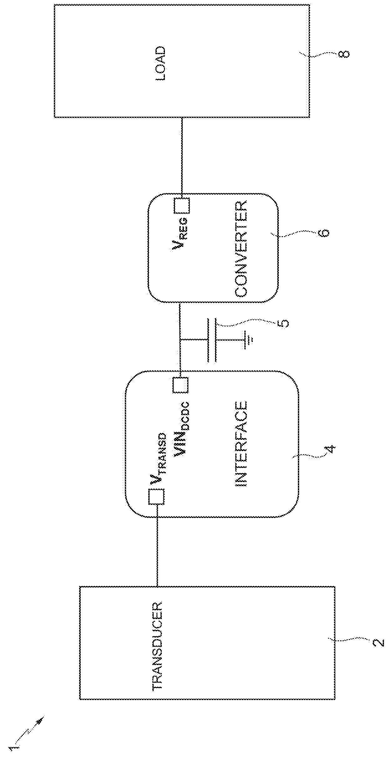
[0036]As illustrated in FIG. 3, an energy harvesting system 10 according to one embodiment of the present solution, comprises in general, and substantially as has been described previously: a transducer 12, in particular a photovoltaic or thermoelectric generator, which generates a transduction signal VTRANSD, in particular a DC voltage or a slowly varying voltage; a harvesting interface 14, which provides a MPPT coupling, receives the transduction signal VTRANSD, on an input terminal 14a, and supplies a harvesting signal VINDCDC, on an output terminal 14b; a storage capacitor 15, which is connected to the output terminal 14b of the harvesting interface 14 and receives the harvesting signal VINDCDC; and a DC-DC converter 16, connected to the storage capacitor 15 for receiving the electrical energy stored and generating at output a regulated signal VREG, which is then supplied to an electrical load (here not illustrated), for its supply or recharge.

[0037]According to one aspect of th...


PUM


Abstract

An electrical-energy harvesting system envisages a transducer for converting energy from an environmental energy source into a transduced signal, an electrical energy harvesting interface for receiving the transduced signal and for supplying a harvesting signal, and an energy storage element coupled to the electrical energy harvesting interface for receiving the harvesting signal. The electrical-energy harvesting system also includes a voltage converter connected to the electrical energy harvesting interface for generating a regulated voltage. The harvesting interface samples an open-circuit voltage value of the transduced signal, generates an optimized voltage value starting from the open-circuit voltage value, and generates an upper threshold voltage and a lower threshold voltage on the basis of the optimized voltage value. The harvesting interface controls the voltage converter in switching mode so that the harvesting signal has a value between the upper and lower threshold voltages in at least one operating condition.

Description

BACKGROUND[0001]1. Technical Field[0002]The present disclosure relates to a high-efficiency energy harvesting interface and to a corresponding energy harvesting system.[0003]2. Description of the Related Art[0004]As is known, systems for harvesting (or scavenging) energy from mechanical or environmental energy sources arouse considerable interest in a wide range of technological fields, for example in the field of portable electronic devices or in the automotive field.[0005]Typically, energy harvesting systems are designed to harvest, store, and transfer energy generated by mechanical or environmental sources to a generic electrical load, which may be supplied, or, in the case of a battery, recharged. These systems thus enable production of electronic apparatuses that operate without a battery, or with a considerable increase in the duration of batteries in the case of apparatuses provided therewith.[0006]For harvesting environmental energy, solar or thermoelectric generators may be...

Claims


Application Information

Patent Timeline
Patent Type & Authority Patents(United States)
IPC IPC(8): H02M3/158H02J7/35
CPCH02M3/158H02J7/35H02J7/32H02J50/001Y02B10/10Y02E10/56H02M3/02
Inventor RAMORINI, STEFANOGASPARINI, ALESSANDROCATTANI, ALBERTO
Owner STMICROELECTRONICS INT NV
Why Eureka
Try Eureka