Oriented film printing plate and manufacturing method for liquid crystal display device
a technology oriented film, which is applied in the field of display device, can solve the problems of reducing the yield of liquid crystal display device, removing the protruding part, and losing it when wiping work is performed, so as to prevent the oriented film thickness from becoming non-uniform, the effect of preventing a reduction in the manufacture yield
- Summary
- Abstract
- Description
- Claims
- Application Information
AI Technical Summary
Benefits of technology
Problems solved by technology
Method used
Image
Examples
embodiment 1
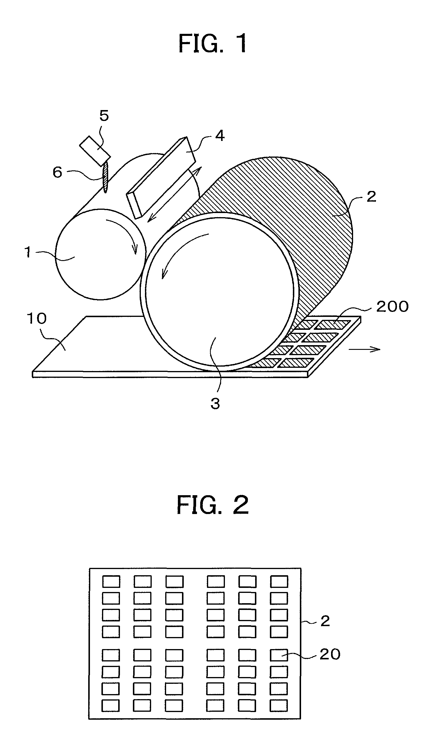
[0033]FIG. 1 is a schematic diagram illustrating an example of a configuration of a flexographic printing system for an oriented film. In FIG. 1, an oriented film material 6 is dipped onto an anilox roll 1 through an injection nozzle 5. The injection nozzle 5 is scanned in an axial direction of the anilox roll 1 so as to uniformly apply the oriented film material 6 onto the anilox roll 1. As the anilox roll 1 rotates, a doctor blade 4 is swung in directions of arrows so as to more uniformly apply the oriented film material 6 onto the anilox roll 1.
[0034]The oriented film material 6 which has been applied onto the anilox roll 1 is transferred to a printing plate 2 wound on a plate cylinder 3 and then is transferred to a mother substrate 10, thereby printing an oriented film 200 onto the mother substrate 10. The printing plate 2 transfers the oriented film to the mother substrate 10 which is traveling in a direction of an arrow while rotating in a direction of an arrow.
[0035]Here, the...
embodiment 2
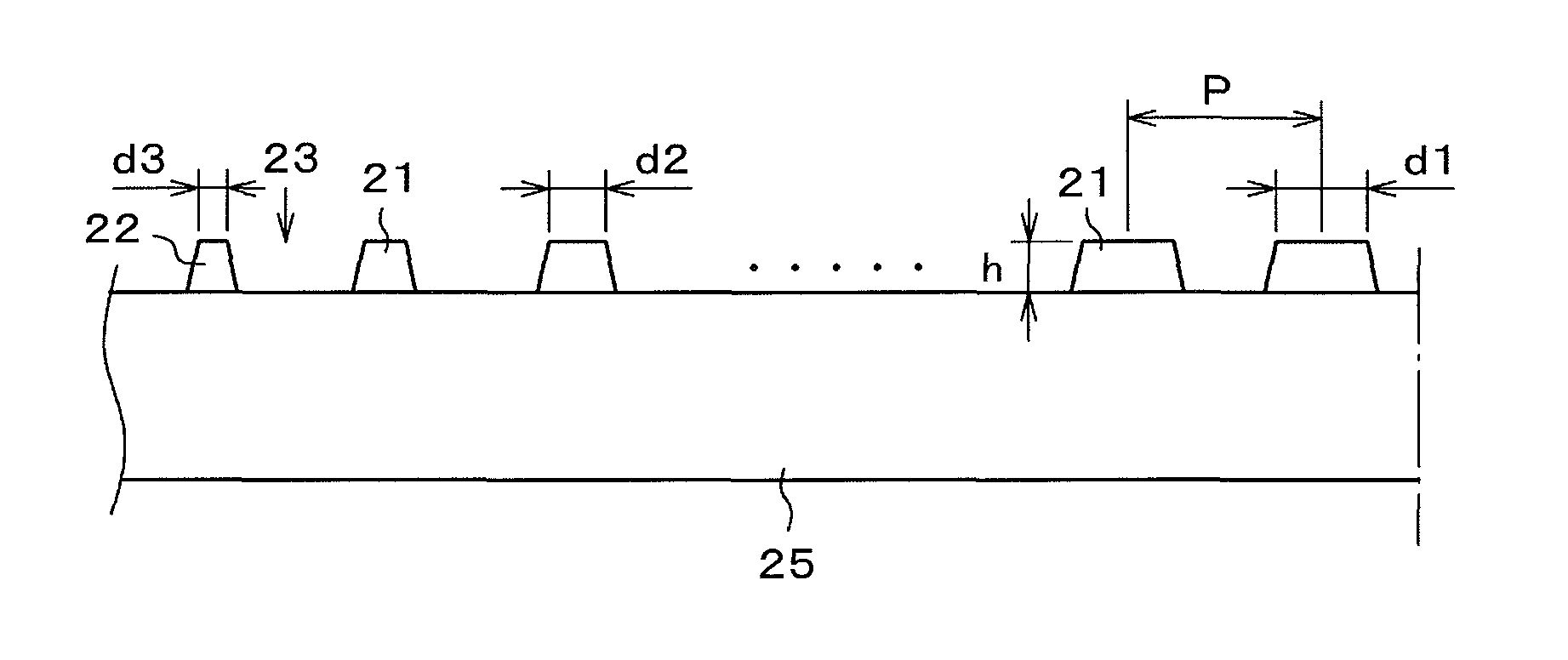
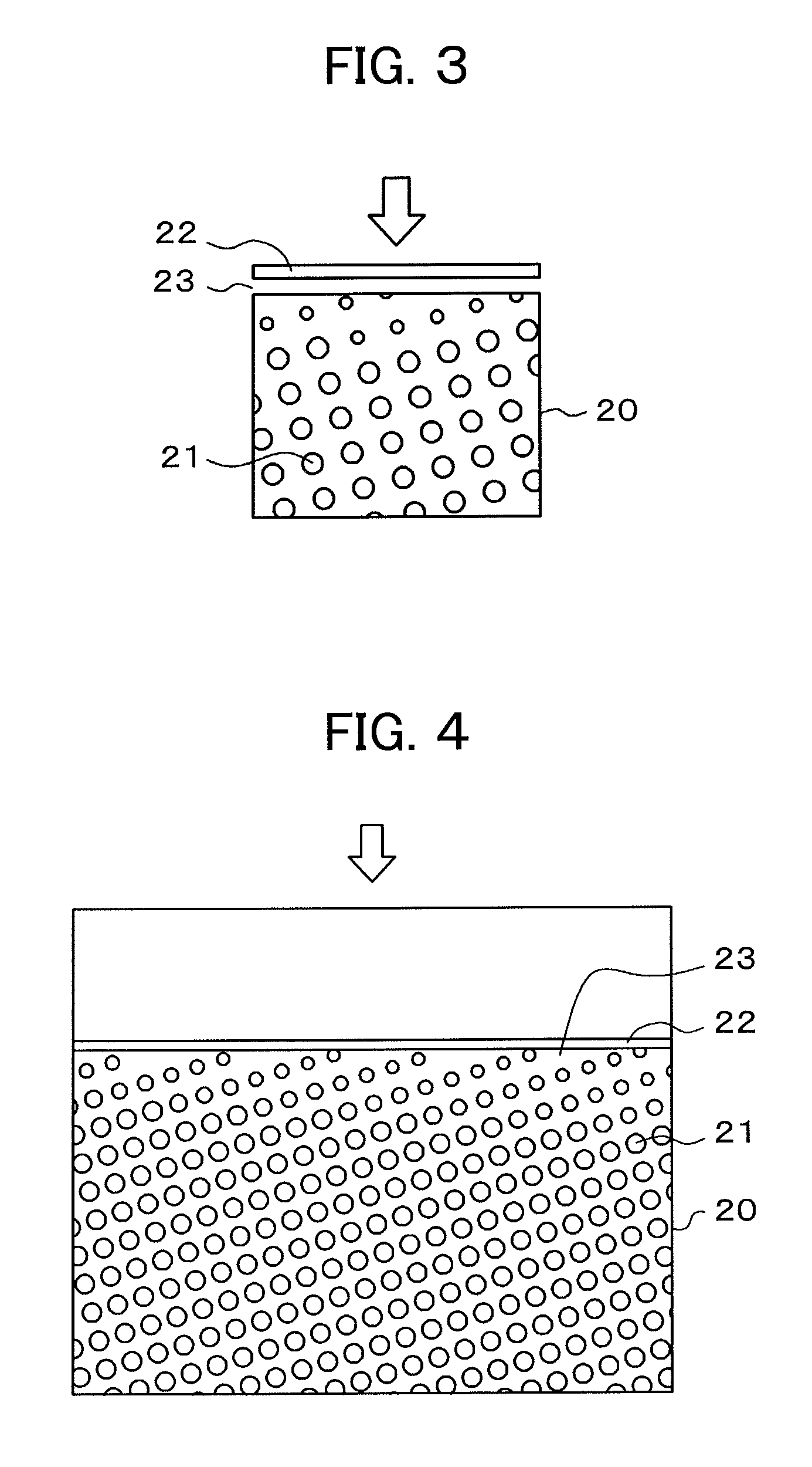
[0049]In Embodiment 1, a case that wiping of the oriented film print pattern 20 is performed only from one direction as illustrated in FIG. 3 has been described. However, in an actual device, in some cases it is desirable to configure so as to perform wiping of the oriented film print pattern 20 from any direction. FIG. 7 illustrates an example of the oriented film print pattern 20 coping with the above-mentioned case. In FIG. 7, the linear bank 22 is formed so as to surround the oriented film print pattern 20 including the protruded parts 21. The space 23 is formed between the bank 22 and the protruded parts 21. Although the space 23 is exaggeratedly illustrated in FIG. 7, it is allowable that a space of an extent that the protruded parts 21 are not formed contiguously to the bank 22 is left in reality.
[0050]In FIG. 7, the diameters of the protruded parts 21 are made larger in the region in the vicinity of the center and smaller in the peripheral region. A way of changing the diame...
PUM
| Property | Measurement | Unit |
|---|---|---|
| diameter | aaaaa | aaaaa |
| diameter | aaaaa | aaaaa |
| width d3 | aaaaa | aaaaa |
Abstract
Description
Claims
Application Information
 - R&D
- Intellectual Property
- Life Sciences
- Materials
- Tech Scout
- Unparalleled Data Quality
- Higher Quality Content
- 60% Fewer Hallucinations
Browse by: Latest US Patents, China's latest patents, Technical Efficacy Thesaurus, Application Domain, Technology Topic, Popular Technical Reports.
© 2025 PatSnap. All rights reserved.Legal|Privacy policy|Modern Slavery Act Transparency Statement|Sitemap|About US| Contact US: help@patsnap.com


