Controller for actuators in microscope lenses

a technology of actuators and microscope lenses, which is applied in the direction of temperatue control, instrumentation, and structural/machine measurement, etc., can solve the problems of inability to achieve continuous movement of several movable elements together, inapplicability to reproducible serial production, and inability to achieve continuous movement of several movable elements as required in microscope objectives, etc., to achieve cost-efficient design construction, increase degree of freedom, and maintain image quality

Active Publication Date: 2016-07-12
CARL ZEISS MICROSCOPY GMBH
View PDF41 Cites 0 Cited by
  • Summary
  • Abstract
  • Description
  • Claims
  • Application Information

AI Technical Summary

Benefits of technology

[0006]Based on said prior art, the invention is based on the task of creating a controller for microscope objectives for correcting the spherical aberration and for the adjustment of particularly hard-to-reach microscope objectives for best imaging quality, and which allows for an automatic adjustment of the varying movable elements of a microscope objective and, therefore, a simple, cost-efficient, user-friendly, and precise compensation, particularly, of cover glass fluctuations and varying bottom thicknesses of Petri dishes for improving the imaging quality.
[0009]A further advantage of the motorized control is the free configuration of the characteristics for travel paths for each motor, which, e.g., can be designed as positioning drive.
[0011]In an example embodiment, the characteristics for the travel paths of the movable elements of the microscope objective are stored in the internal control unit, whereby correcting of the imaging quality and focusing can be executed in accordance with the various characteristics for travel paths. As a result, every microscope objective can be switched on the stand, allowing for the use of a multiple turret or a switch of objectives during the measuring process. Furthermore, the storage of the characteristics for travel paths of the movable elements of every microscope objective in the internal control unit prevents collisions of the starting and end points of the travel paths of the individual movable elements, which vary due to mechanically caused tolerances.
[0013]With the controller, according to the invention, the mechanical advantages of the thread adjustment can be used in such a way that in addition to the heretofore executed linear movements of the movable elements, said movable elements can also be moved along programmable curved paths, allowing for increased degrees of freedom for the layout of the optical design of a objective, which, among others, allow for a more cost-efficient construction of the design.
[0014]A further advantage of utilizing the controller is the option of focusing into the sample (internal focusing) while maintaining the image quality through appropriate adjustment of the movable elements. This is particularly significant for focusing with a microscope objective through a cover glass or the bottom of a Petri dish into an aqueous solution since the correcting and focusing position of the microscope objective must be adjusted due to the dispersion of light in water. As a result, the application of a microscope objective is further expanded. Until now it has only been possible to adjust the spherically corrected focal point of a microscope objective for varying cover glass thicknesses and / or immersion media directly at the cover glass or bottom of a Petri dish.

Problems solved by technology

The disadvantage of using curves can be seen in the manufacture of the surfaces of said curves.
Even though it is technically possible to grind a groove that is shaped as a curve, it is not applicable for reproducible serial production.
Even though a quick movement can be achieved via lever adjustment, a continuous movement of several movable elements together, as required in microscope objectives, cannot be achieved.

Method used


Image

  • Controller for actuators in microscope lenses
  • Controller for actuators in microscope lenses
  • Controller for actuators in microscope lenses

Examples


first embodiment

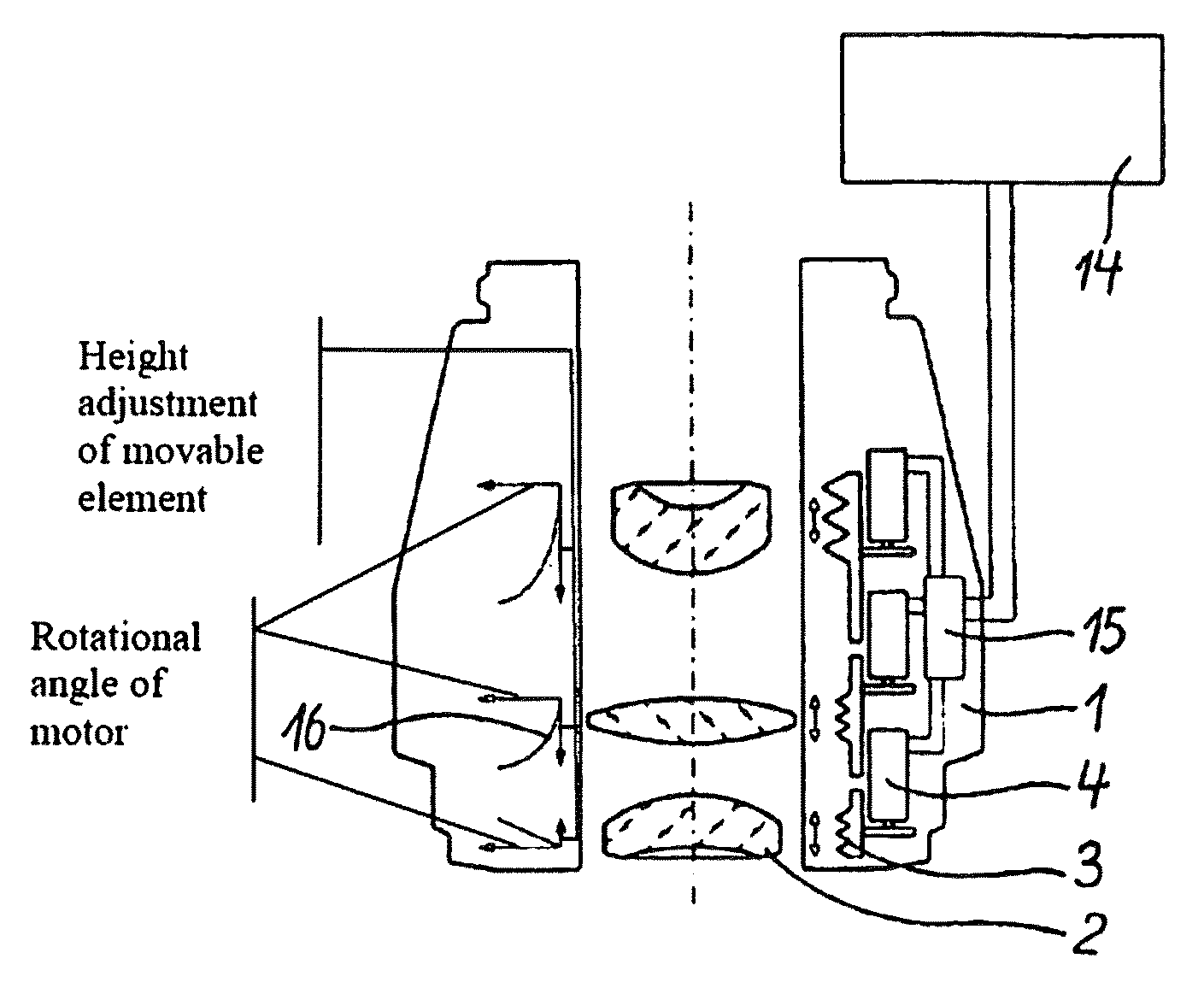
[0021]FIG. 1 depicts the cutaway view of the controller, according to the invention, for a microscope objective 1. In order to adjust hard-to-reach microscope objectives 1 easily for the best imaging quality, it is advantageous if, for example, at least two movable elements 2 of the microscope objective 1, including mounted lenses or lens groups which are controllable through respective motors 4, are movable in axial direction via respectively assigned adjusting rings 3 along the optical axis of the microscope objective 1. Positioning drives, piezo motors, or ultrasonic motors can also be utilized as drives.

[0022]In the embodiment in accordance with FIG. 1, every movable element 2 is positioned via an adjusting ring 3 rotationally driven, by means of a motor 4, respectively. Thereby, the individual motors 4 can be controlled in such a way that the respective controlled movable element 2 travels on an axial, linear path and / or an axial curved path.

[0023]During the axial movement of a...

second embodiment

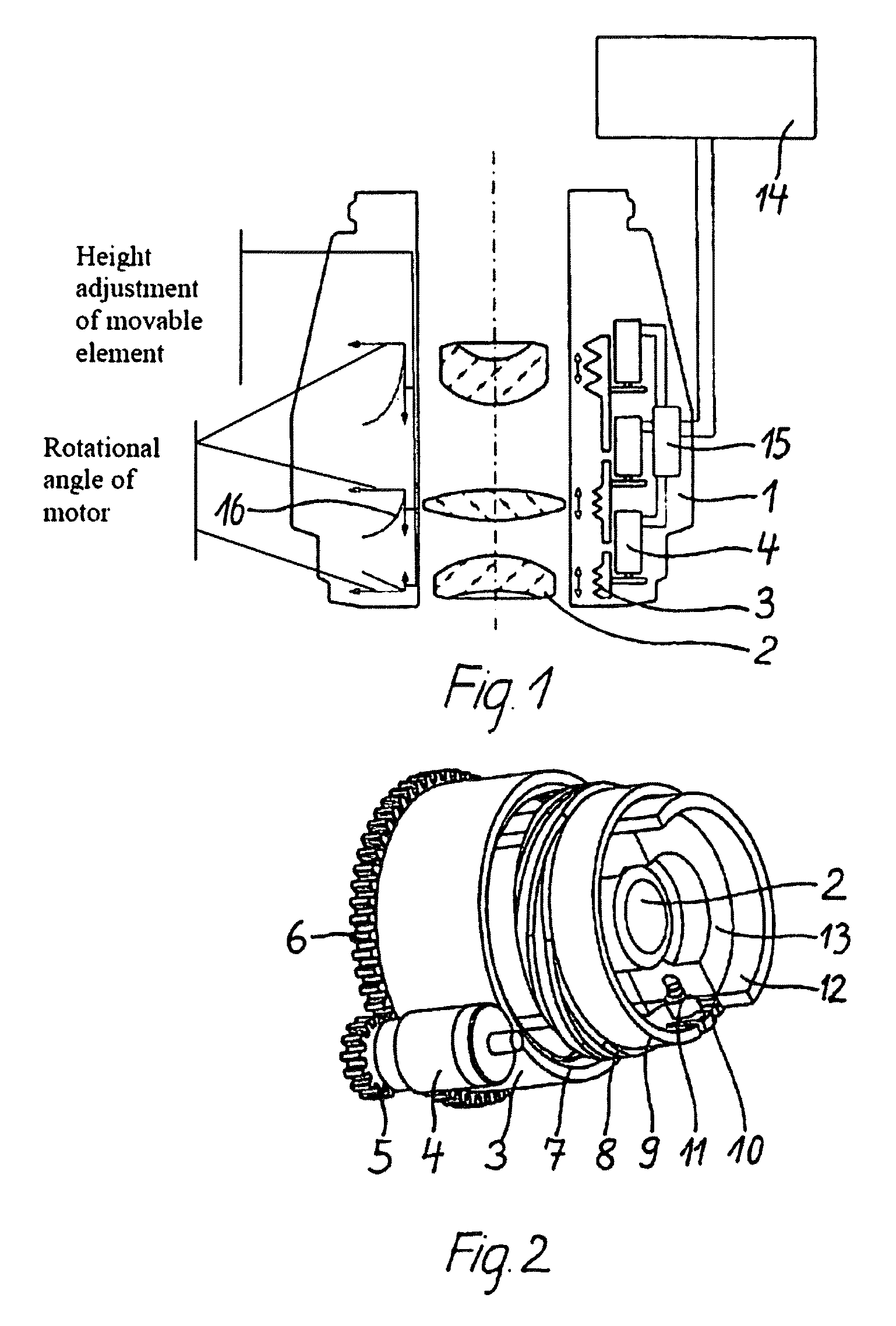
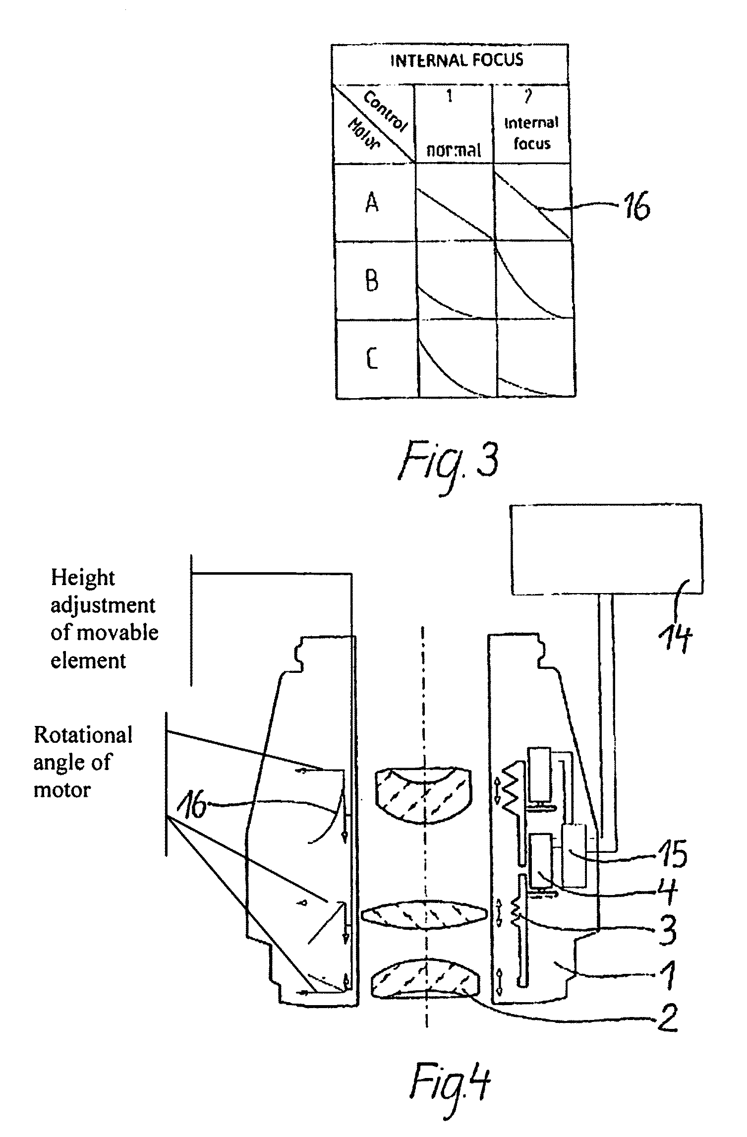
[0024]According to FIG. 4, the adjusting rings 3 are partially coupled in a second embodiment via the motors 4 or completely coupled and rotationally moved through a motor 4 in another embodiment. The transmitting of the rotary movement of the motors 4 onto the movable elements 2 is advantageously effected via a gear unit, either via a gear train (see FIG. 2) or a tooth belt drive. The motor 4 drives the adjusting ring 3 via a pinion 5 and a sprocket 6. Via a spring package, not shown herein, the adjusting ring 3 is pressed against a fixed structure and can therefore only be moved rotationally. Internally, the adjusting ring 3 exhibits an internal thread 7; the internal thread 7 engages in an external thread 8 of an inner bushing 9, wherein a lug 10 is positioned. Said lug 10 is led via an elongated hole 11 into a fixed bushing 12 and is connected with the bushing for the lens holder 13. The bushing for the lens holder 13 with the lens positioned inside results in the movable elemen...


PUM


Abstract

A controller for microscope lenses for correcting spherical aberration and for adjusting particularly difficult to access microscope lenses to an optimum of imaging quality, enabling automatic adjustment of the different actuators of a microscope lens, to effect a simple, cost-effective, user-friendly, and precise balance, particularly of cover slip deviations and different base thicknesses of Petri dishes for the purposes of increasing imaging quality. At least two movable elements of a microscope objective supporting lenses or lens groups, are provided in a movable manner in the axial direction along the optical axis of the microscope objective relative to the housing of the microscope lens in a motor-actuated manner by way of respective adjusting rings. A controller externally controlled and disposed in the microscope lens is provided for storing different characteristic curves for paths of motion of the movable elements.

Description

PRIORITY CLAIM[0001]The present application is a National Phase entry of PCT Application No. PCT / EP2009 / 003893, filed May 30, 2009, which claims priority from German Application Number 102008026774.0, filed Jun. 4, 2008, 2008, the disclosures of which are hereby incorporated by reference herein in their entirety.FIELD OF THE INVENTION[0002]The invention relates to a controller for movable elements in microscope objectives for the adjustment of particularly hard-to-reach microscope objectives for ideal imaging quality and means for storing the adjustment movements of the movable elements.BACKGROUND[0003]It is known, as described in DE 198 04 470 C1, that for the adjustment to varying cover glass thicknesses, microscope objectives exhibit several lens group mounts, whereby one is designed as a correcting mount for the adjustment to varying cover glass thicknesses and axially movable between the lens group mounts, which are stationary with regard to the objective, whereby the correctin...

Claims


Application Information

Patent Timeline
Patent Type & Authority Patents(United States)
IPC IPC(8): G02B7/00G02B7/02G02B21/02G02B21/24G02B27/00
CPCG02B7/023G02B21/02G02B21/241G02B27/0068
Inventor FAHLBUSCH, INGOHERBST, GEORG
Owner CARL ZEISS MICROSCOPY GMBH
Why Eureka
Try Eureka