
Pumping systems

a pumping system and pulsation reduction technology, applied in the direction of rotary/oscillating piston pump components, machines/engines, liquid fuel engines, etc., can solve the problems of poor and/or inconsistent product quality, pulsation of flow, damage to piping, etc., and achieve the effect of reducing the peak amplitude of such cyclic pressure fluctuations

Active Publication Date: 2016-07-19
HILL KEVIN THOMAS
View PDF40 Cites 3 Cited by
  • Summary
  • Abstract
  • Description
  • Claims
  • Application Information

AI Technical Summary

Benefits of technology

[0009]It is a further object and feature of the present invention to provide such a system that provides a direct means for reducing flow pulsation within positive displacement pumps. It is another object and feature of the present invention to provide increased gear pump performance by reducing the tendency of a given pump to experience cavitation at elevated pump speeds. It is another object and feature of the present invention to provide such a system having improved protection from unsafe overpressures, which can arise when portions of the asphaltic materials within the pumping system fail to reach or maintain the necessary molten-fluid state. It is another object and feature of the present invention to provide such a system using a set of interchangeable modular components to provide a highly adaptable asphalt pumping device. It is a further object and feature of the present invention to provide such a system that utilizes a symmetrical physical geometry to increase modularity within the mateable components of the system. A further primary object and feature of the present invention is to provide such a system that is efficient, inexpensive, and useful. Other objects and features of this invention will become apparent with reference to the following descriptions.SUMMARY OF THE INVENTION
[0027]Additionally, it provides such a system further comprising: at least one active controller structured and arranged to actively control the operation of such at least one flow modulator; wherein such at least one active controller comprises at least one coordinator structured and arranged to coordinate the operational timing of such at least one flow modulator with cyclic pressure fluctuations exhibited by such at least one gear pump during operation; wherein such at least one coordinator is configured to enable a maximum flow volume, through such at least one fluid pathway, coinciding with both maximum elevated positive pressure levels and maximum reduced positive pressure levels within such at least one discharge-pressure region; wherein such at least one coordinator is configured to enable a minimum flow volume, through such at least one second fluid pathway, coinciding with pressure transitions, within such at least one discharge-pressure region, between such maximum elevated positive pressure levels and such maximum reduced positive pressure levels; wherein such controlled modulation of the flow of the viscous molten fluids through such at least one fluid pathway assists in reducing peak amplitudes of such cyclic pressure fluctuations exhibited by such at least one gear pump during operation.

Problems solved by technology

Flow pulsation during the operation of such pumps is often associated with damage to piping, meters, valves, and instrumentation.
In addition, flow pulsation in essential production processes often contributes to poor and / or inconsistent product quality, thus producing off-spec waste or inferior final results.
Particularly problematic is the reduced accuracy of flow metering and measurement devices (especially in pulse-sensitive coriolis flow meter apparatus) that result from fluid pulsation.
Gear pump cavitation is associated with reduced pumping performance and erosion of internal pumping surfaces.
Cavitation generally results from the sudden formation and collapse of low-pressure bubbles in the fluid being pumped.
Numerous safety hazards arise from the handling of asphalt in an elevated temperature.
Asphalt has a large thermal capacity and therefore poses a high potential for serious injury should an uncontrolled release of the materials occur.
Conventional asphalt-pump designs provide limited or marginal pressure safety during operation, and are not readily modifiable using straightforward engineering.
Furthermore, conventional asphalt-pump designs have remained substantially unchanged over time and currently offer little in terms of adaptability / field configurability.

Method used


Image

  • Pumping systems
  • Pumping systems
  • Pumping systems

Examples


Embodiment Construction

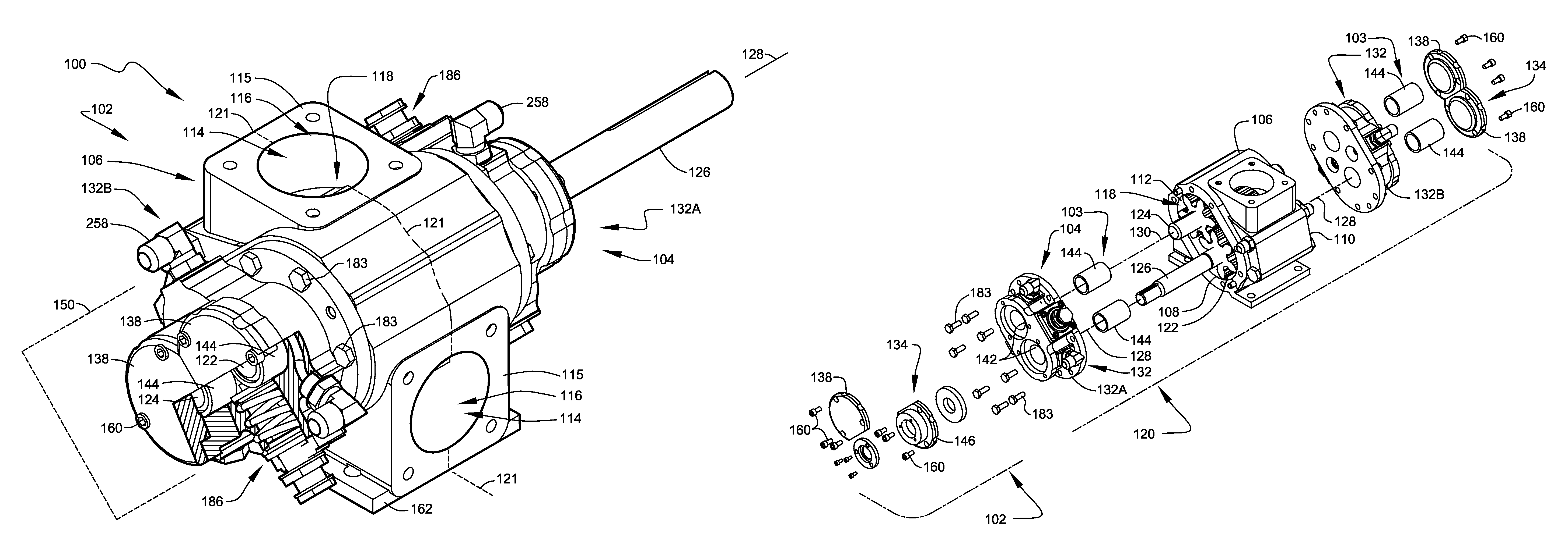
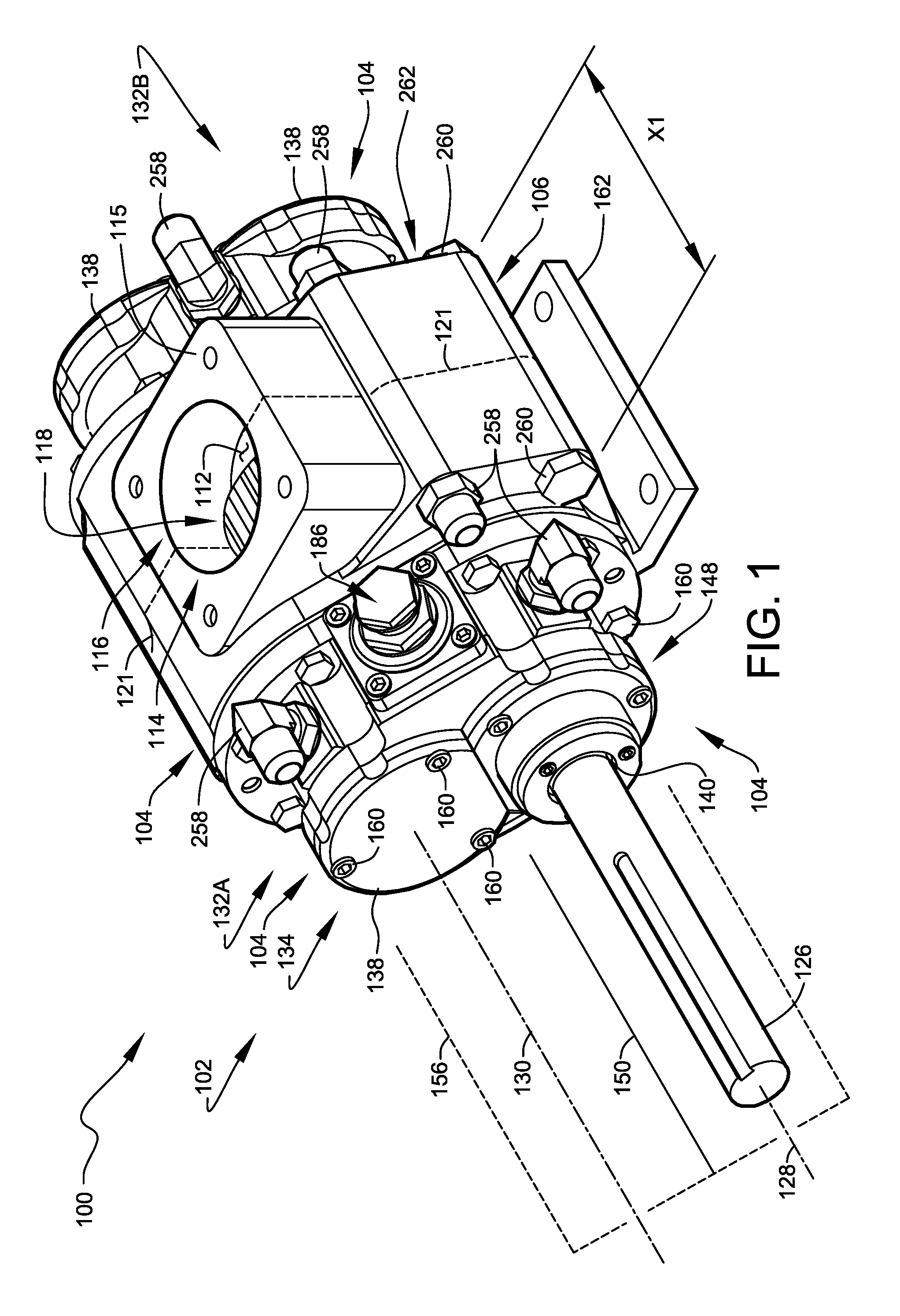
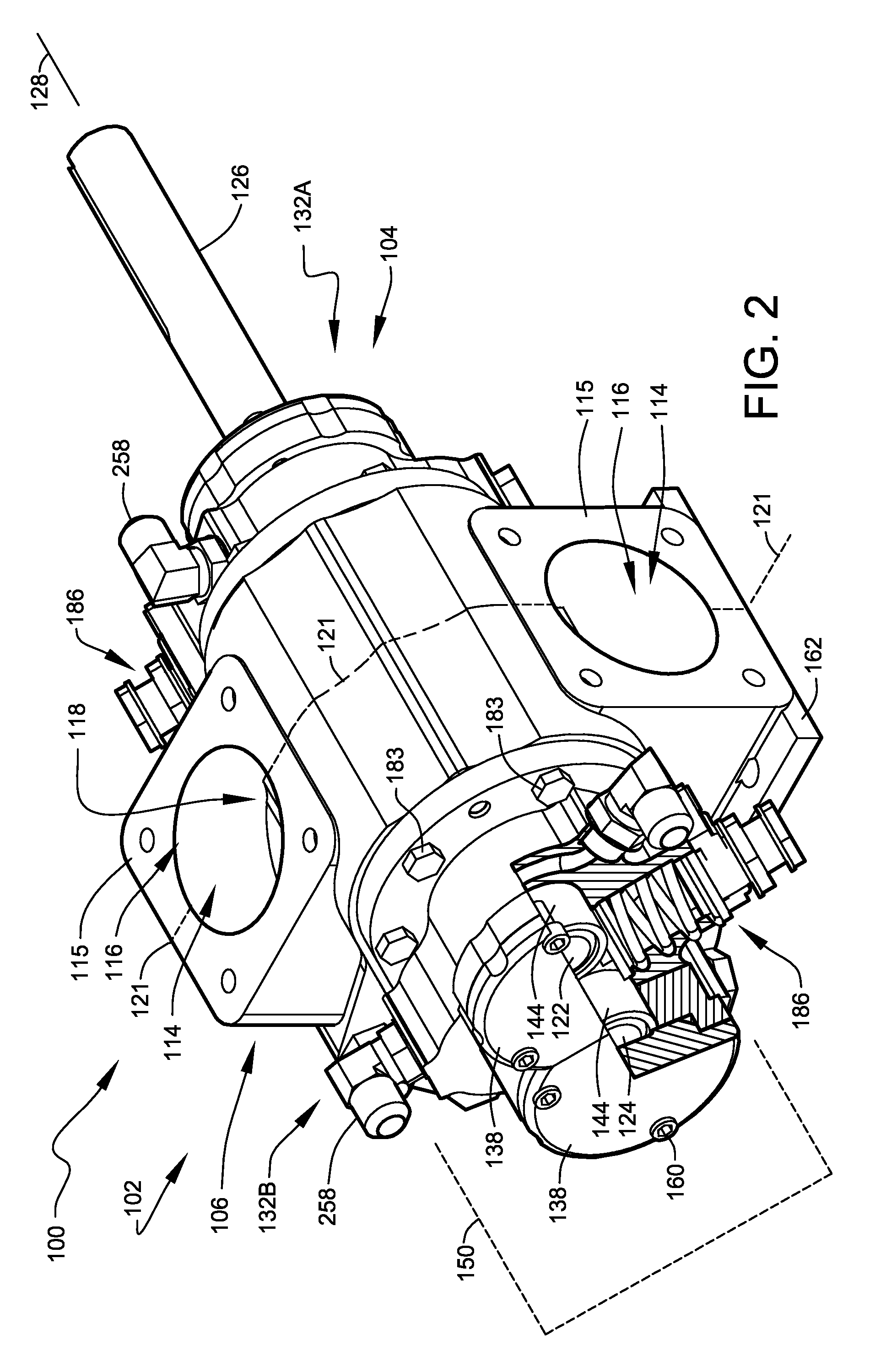
[0062]FIG. 1 shows a shaft-side perspective view illustrating modular-component pump 102, according to a preferred embodiment of the present invention. FIG. 2 shows a second perspective view, in partial section, illustrating the opposing end of modular-component pump 102 of FIG. 1. The depicted modular-component pump 102 is presented as one preferred example embodiment representative of preferred pump embodiments configurable within asphalt pumping system 100.

[0063]Modular-component pump 102 is designed to enhance safety and reduce costs associated with the design and implementation of pumping system for viscous molten fluids, such as, hot asphalt and similar bituminous materials. Preferred embodiments of asphalt pumping system 100, preferably including modular-component pump 102, are assembled from groupings of selectable modular components 104 of the system.

[0064]FIG. 3 is an exploded view showing the preferred grouping of modular components 104 making up modular-component pump 10...


PUM


Abstract

A modular symmetrical asphalt pumping system providing a series of field-configurable gear pumps and meters usable to safely and efficiently pump viscous molten fluids, such as, asphalt and similar bituminous materials. The system utilizes highly symmetrical physical geometries and modular components to allow for the development of multiple pump configurations using a reduced quantity of parts. Preferred arrangements of the system reduce pump pulsing and cavitation.

Description

CROSS-REFERENCE TO RELATED APPLICATIONS[0001]The present application is related to and claims priority from prior provisional application Ser. No. 61 / 355,515, filed Jun. 16, 2010, entitled “MODULAR SYMMETRICAL ASPHALT PUMPING SYSTEMS”; and, this application is related to and claims priority from prior provisional application Ser. No. 61 / 361,887, filed Jul. 6, 2010, entitled “PUMPING SYSTEMS”; and, this application is related to and claims priority from prior provisional application Ser. No. 61 / 429,412, filed Jan. 3, 2011, entitled “PUMPING SYSTEMS”, the contents of all of which are incorporated herein by this reference and are not admitted to be prior art with respect to the present invention by the mention in this cross-reference section.BACKGROUND[0002]This invention relates to reduced-pulsation pumping systems. More particularly, this invention relates to pulsation-reducing pumping systems which provide superior pumping capability through the reduction of fluid pulsations and cav...

Claims


Application Information

Patent Timeline
Patent Type & Authority Patents(United States)
IPC IPC(8): F04C2/00F04C2/14F04C13/00F04C15/00
CPCF04C2/14F04C13/002F04C15/0049F04C2220/24F04C2240/70
Inventor HILL, KEVIN THOMAS
Owner HILL KEVIN THOMAS
Learn More