Apparatus for quantitative measurements of stress distributions from mechanoluminescene materials

a mechanoluminescent material and apparatus technology, applied in the direction of mechanical excitation analysis, force measurement by measuring optical property variation, instruments, etc., can solve the problems of limited strain gauges, limited application of ml material monitoring sensors, and limited strain gauges

Inactive Publication Date: 2016-07-19
THE UNIVERSITY OF AKRON
View PDF9 Cites 4 Cited by
  • Summary
  • Abstract
  • Description
  • Claims
  • Application Information

AI Technical Summary

Benefits of technology

[0013]In an eighth embodiment, the present invention provides an apparatus as in any of the first through seventh embodiments, wherein the chamber blocks a substantial amount of external light from entering the enclosure of the chamber.
[0014]In a ninth embodiment, the present invention provides an apparatus as in any of the first through eighth embodiments, wherein the chamber is sealed onto the surface and blocks all external light from entering the enclosure of the chamber.
[0018]In a thirteenth embodiment, the present invention provides a method of using an apparatus for measuring mechanoluminescent light comprising the steps of providing a structure having mechanoluminescent material thereon; providing a chamber having an imaging sensor, where the chamber defines an enclosure for the portion of the structure to be monitored and provides an opening fitted onto the structure; photoexciting the mechanoluminescent material; allowing the mechanoluminescent material to produce mechanoluminescence light; and capturing images of the mechanoluminescence light.

Problems solved by technology

Existing applications of using sensors for monitoring ML materials are limited.
For instance, strain gauges are generally limited to point-by-point measurements.
Also, existing sensors are generally not capable of revealing full field visualization of stresses.

Method used


Image

  • Apparatus for quantitative measurements of stress distributions from mechanoluminescene materials
  • Apparatus for quantitative measurements of stress distributions from mechanoluminescene materials

Examples


Embodiment Construction

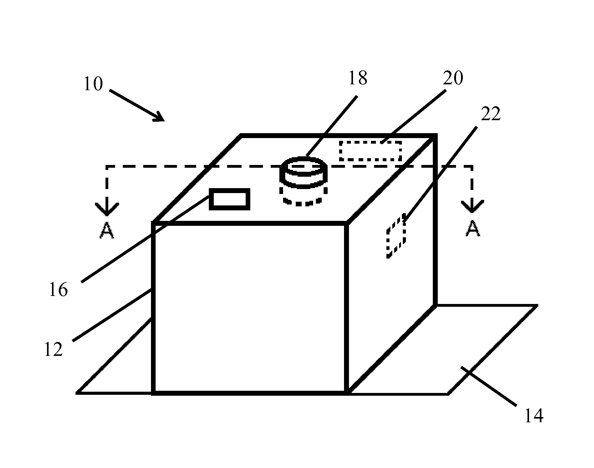
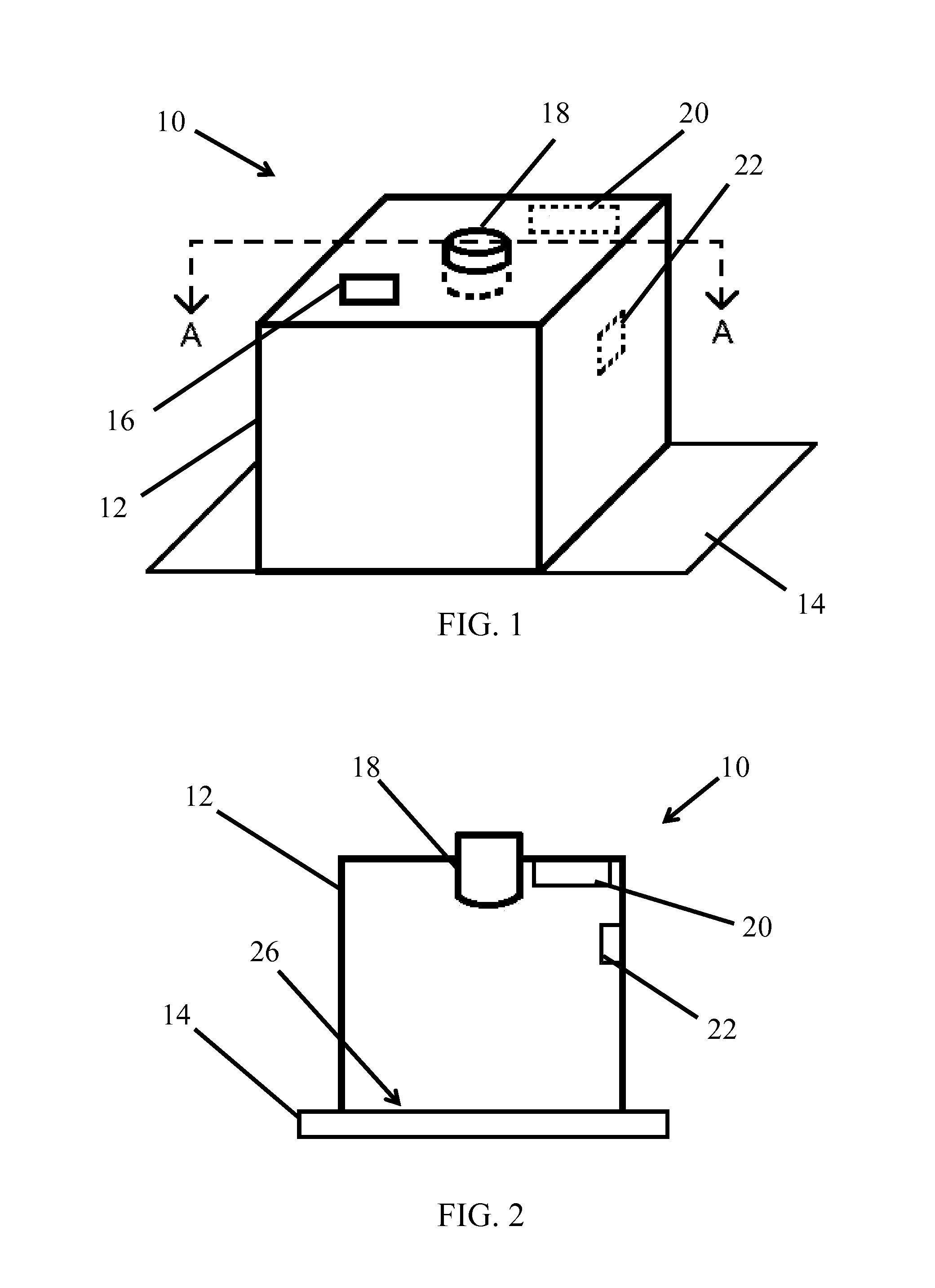
[0023]An apparatus, generally indicated by the numeral 10, of the present invention includes chamber 12 that is capable of measuring the mechanoluminescence of a structure 14 having a mechanoluminescent material thereon. Chamber 12 measures the quantitative stress or strain distributions of a mechanoluminescent material by analyzing the intensity of mechanoluminescence light.

[0024]Chamber 12 can include various components for performing various roles. Chamber 12 comprises one or more of the following: an electronic controller 16, an imaging sensor 18, a light source 20, and a thermocouple 22. In one or more embodiments, an apparatus 10 consists of a chamber 12 consisting of an electronic controller 16, an imaging sensor 18, a light source 20, and a thermocouple 22. In one or more embodiments, an apparatus 10 comprises a chamber 12 comprising an electronic controller 16, an imaging sensor 18, a light source 20, and a thermocouple 22.

[0025]As shown in the figures, chamber 12 defines a...


PUM

PropertyMeasurementUnit
photoexcitation wavelengthaaaaaaaaaa
stress distributionaaaaaaaaaa
temperatureaaaaaaaaaa

Abstract

An apparatus for measuring mechanoluminescent light includes a chamber defining an enclosure for a portion of a structure to be monitored and providing an opening fitted onto the structure. The structure has a mechanoluminescent material thereon. The apparatus further includes an imaging sensor positioned and configured to take images of the mechanoluminescent material and an electronic controller in wired or wireless communication with the imaging sensor, the electronic controller being capable of controlling the properties of the imaging sensor and processing the images of the mechanoluminescent material.

Description

CROSS-REFERENCE TO RELATED APPLICATION[0001]This application claims priority to U.S. Provisional Patent Application No. 61 / 889,090 filed on Oct. 10, 2013, the contents of which are incorporated herein by reference.FIELD OF THE INVENTION[0002]The present invention generally relates to an apparatus for measuring the mechanoluminescence of a mechanoluminescent material. The present invention further relates to an apparatus that measures the quantitative stress or strain distributions of a mechanoluminescent material using mechanoluminescence light intensity. The present invention further relates to an apparatus having a mechanoluminescent material within a chamber, where the apparatus photoexcites the mechanoluminescent material, takes images of the mechanoluminescent material, and monitors environmental conditions within the chamber.BACKGROUND OF THE INVENTION[0003]It is previously known to use mechanoluminescence (ML) materials for the visualization of stress or crack distributions t...

Claims


Application Information

Patent Timeline
Patent Type & Authority Patents(United States)
IPC IPC(8): G01B11/16G01N21/88G01L1/24
CPCG01N21/8803G01L1/24G01N2201/061G01N21/8806G01N21/91G01N21/70
Inventor YUN, GUNJIN
Owner THE UNIVERSITY OF AKRON
Why Eureka
Try Eureka