
Projector system and control method thereof

a projector and control method technology, applied in the field of projector systems and control methods thereof, can solve the problems that users cannot reach the upper portion of the projection surface in some cases, and achieve the effects of reducing image, improving convenience, and high convenien

Active Publication Date: 2016-07-19
SEIKO EPSON CORP
View PDF10 Cites 3 Cited by
  • Summary
  • Abstract
  • Description
  • Claims
  • Application Information

AI Technical Summary

Benefits of technology

The patent describes a projector that can detect the user's height and adjust the size of an image based on the user's input using a light-emitting pen. The user can draw or enter the image at different positions within the detection area, and the projector will automatically reduce the image to the appropriate size. When the user moves out of the detection area or if no user is detected, the image will automatically restore to its original size, providing convenience to the user. The technical effects of this use a ranging module and include improved convenience and a simplified user experience.

Problems solved by technology

In such an interactive system, however, when the user performs an input operation with the electronic pen or the like, the user cannot reach an upper portion of a projection surface in some cases.
In such a case, the user can cope with the situation by standing on a platform or the like, which is inconvenient.

Method used


Image

  • Projector system and control method thereof
  • Projector system and control method thereof
  • Projector system and control method thereof

Examples


first embodiment

[0027]As a first embodiment, a hanging-type projector that measures a height of a user, reduces an image according to the height, and projects the image, and an interactive system will be described below.

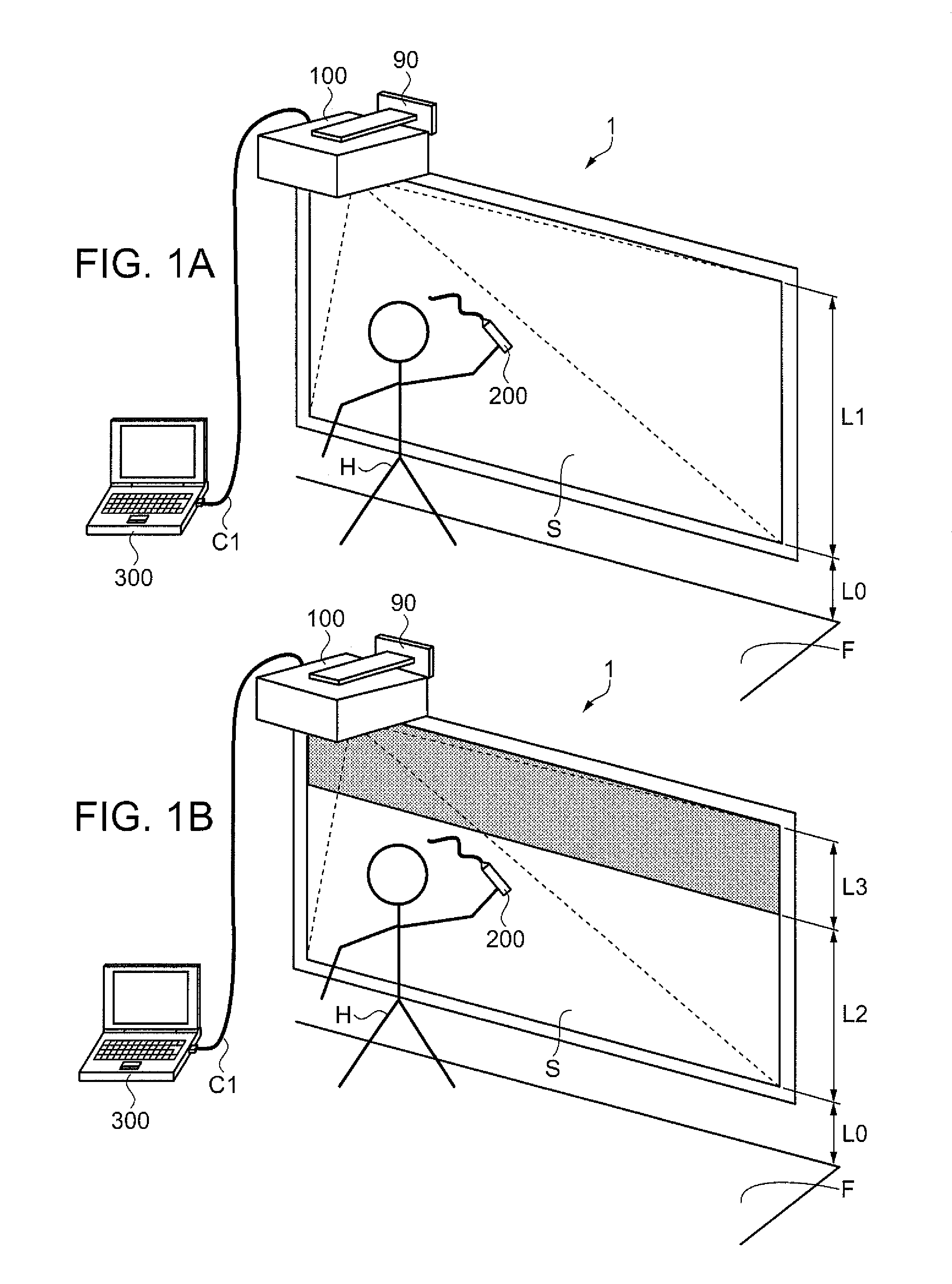
[0028]FIGS. 1A and 1B are explanatory views showing modes of use of the interactive system according to the first embodiment, in which FIG. 1A is an explanatory view showing a normal mode of use; and FIG. 1B is an explanatory view showing a mode of use in which a projection image is reduced.

[0029]FIGS. 1A and 1B show a form in which a user H makes a presentation. As shown in FIGS. 1A and 1B, in the interactive system 1 of the embodiment, a projector 100, a light-emitting pen 200 as a pointer that sends a light signal, a personal computer (PC) 300, the user H who holds the light-emitting pen 200, and a projection surface S such as a whiteboard are shown.

[0030]The projector 100 is attached via an attaching member 90 to a wall surface above the projection surface S and projects an imag...

second embodiment

[0091]In a second embodiment, a projector that enables the user H to manually specify, using the light-emitting pen 200, a height to which an image is reduced, and an interactive system will be described. In this case, the projector 100 does not need a ranging module.

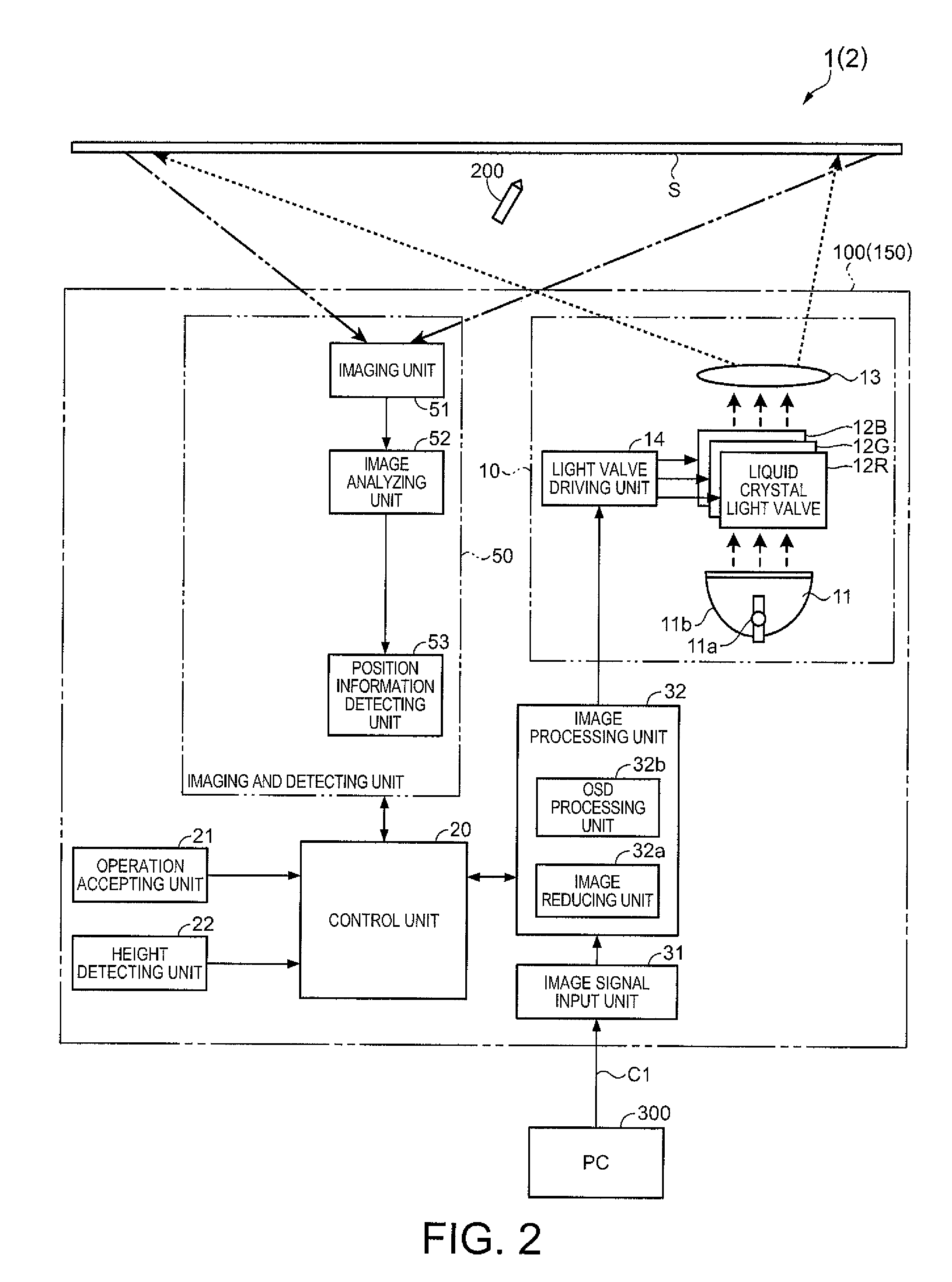
[0092]A configuration of a projector 150 according to the second embodiment is similar to that of the projector 100 of the first embodiment (refer to FIG. 2). Also a configuration of an interactive system2 according to the second embodiment is similar to that of the interactive system 1 of the first embodiment (refer to FIG. 2). Therefore, the descriptions thereof are omitted.

[0093]First, a procedure of reducing an image (image data) using the light-emitting pen 200 will be described.

[0094]FIGS. 9A and 9B are explanatory views of image data of the projector 150 of the second embodiment, in which FIG. 9A is an explanatory view of normal image data; and FIG. 9B is an explanatory view of reduced image data.

[0095]In image d...

modified example 1

[0110]In the embodiments, when the image reducing unit 32a reduces an image (image data), the image is reduced in the vertical direction. However, the image may be reduced in the lateral direction in addition to the vertical direction. In this case, it is preferable that the image is reduced with the aspect ratio of the original image being maintained. This makes it possible to avoid the distortion of a character, a graphic, or the like displayed on the image. Moreover, by detecting also the position of the user H in the lateral direction, an image may be reduced in the lateral direction so that the image is displayed at a place where the user H easily performs pointing.


PUM


Abstract

A projector system includes: a position detecting unit that detects a pointed position of a pointer on a projection surface; a drawing unit that performs drawing on the projection surface according to the pointed position detected by the position detecting unit; a height detecting unit that detects a height of a user of a projector; and a display changing unit that changes, according to the user's height detected by the height detecting unit, at least one of a shape of the image projected onto the projection surface and a display position of the image on the projection surface.

Description

[0001]The entire disclosure of Japanese Patent Application No. 2013-1588, filed Jan. 9, 2013 is expressly incorporated by reference herein.BACKGROUND[0002]1. Technical Field[0003]The present invention relates to a projector system and a control method thereof.[0004]2. Related Art[0005]Heretofore, an interactive system has been proposed, in which an image based on an image signal output from a computer or the like is displayed on a screen or the like by a projector, a user's operation performed on a projection image using an electronic pen is detected by the projector, and an image based on information relating to the user's operation is generated and displayed (for example, JP-A-2011-140154).[0006]In such an interactive system, however, when the user performs an input operation with the electronic pen or the like, the user cannot reach an upper portion of a projection surface in some cases. In such a case, the user can cope with the situation by standing on a platform or the like, w...

Claims


Application Information

Patent Timeline
Patent Type & Authority Patents(United States)
IPC IPC(8): G09G5/00G06F3/042G06F3/041G06F3/00G03B21/14G06T3/40G06F3/0484G06F3/0488
CPCG06T3/40G03B21/14G06F3/005G06F3/0416G06F3/0425G06F3/04845G06F3/04883
Inventor HONDA, YASUHIROOZAWA, TAKASHI
Owner SEIKO EPSON CORP
Learn More