Eye gaze tracking

a technology of eye gaze and tracking, applied in the field of eye gaze tracking, can solve the problems of inflexible solution, large calibration cost, and errors in eye gaze tracking, and achieve the effect of simple and easy eye gaze tracking

Inactive Publication Date: 2016-07-26
ITU BUSINESS DEV AS
View PDF15 Cites 7 Cited by
  • Summary
  • Abstract
  • Description
  • Claims
  • Application Information

AI Technical Summary

Benefits of technology

[0008]The object of the invention is to find a simple and easy eye gaze tracking method, which solves or at least reduces the above drawbacks.
[0014]Thereby calibration of the camera, such as knowledge of the exact position and zoom level of the camera, is avoided. Further, it is not necessary to know the position of light sources. This results in a much more flexible and user friendly system being easier to set up and less expensive than known systems.
[0015]Further, the method is robust to head position, since the user does not have to stay in a fixed position
[0016]Further, the lights and camera can be positioned in any position, making the method very flexible.
[0018]Further, the method can be used with all kinds of light sources (focal, linear circular) and also light from the screen can be used as light source (i.e. no external light sources needed). This results in a less expensive system.
[0019]Further, since no calibration of the camera is needed, the method is more flexible and the user can change the zoom of the camera without affecting the result.

Problems solved by technology

Known systems typically require a lot of cumbersome calibration both in relation to the positioning of the camera and the light sources, and therefore a system for eye gaze tracking without calibrated cameras, direct measurements of specific users' eye geometries or requiring the user to visually track a cursor traversing a known trajectory is needed.
Problems with this solution are that when using one camera, calibration comprising determining the distance between eye and camera is required, but since this distance might change during use, it will result in errors in the eye gaze tracking.
Further, when using this method it is necessary to know the exact position of the light sources, which makes the solution quite inflexible.

Method used


Image

  • Eye gaze tracking
  • Eye gaze tracking
  • Eye gaze tracking

Examples


Embodiment Construction

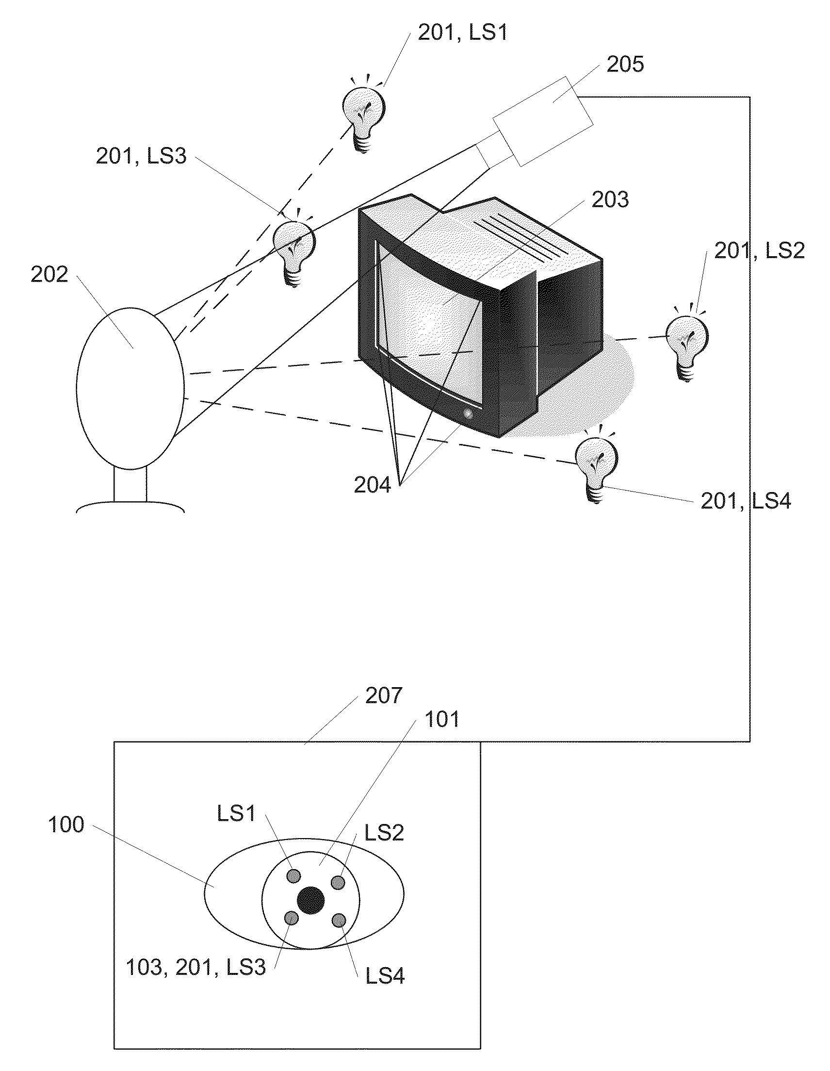
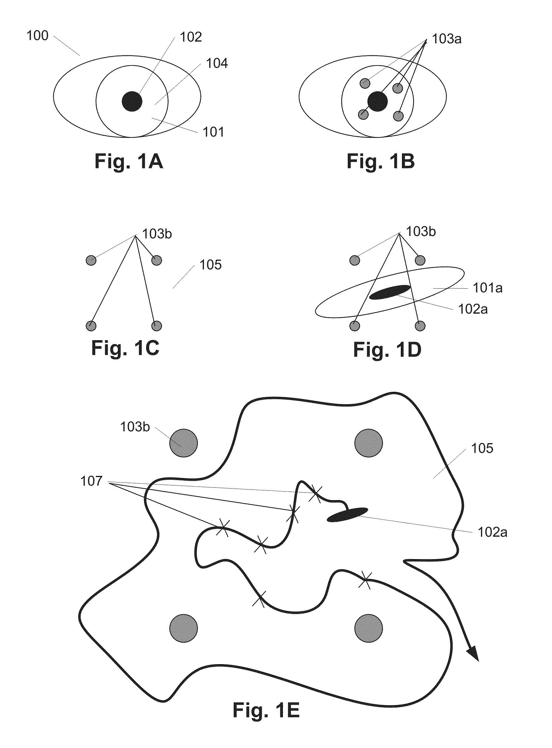
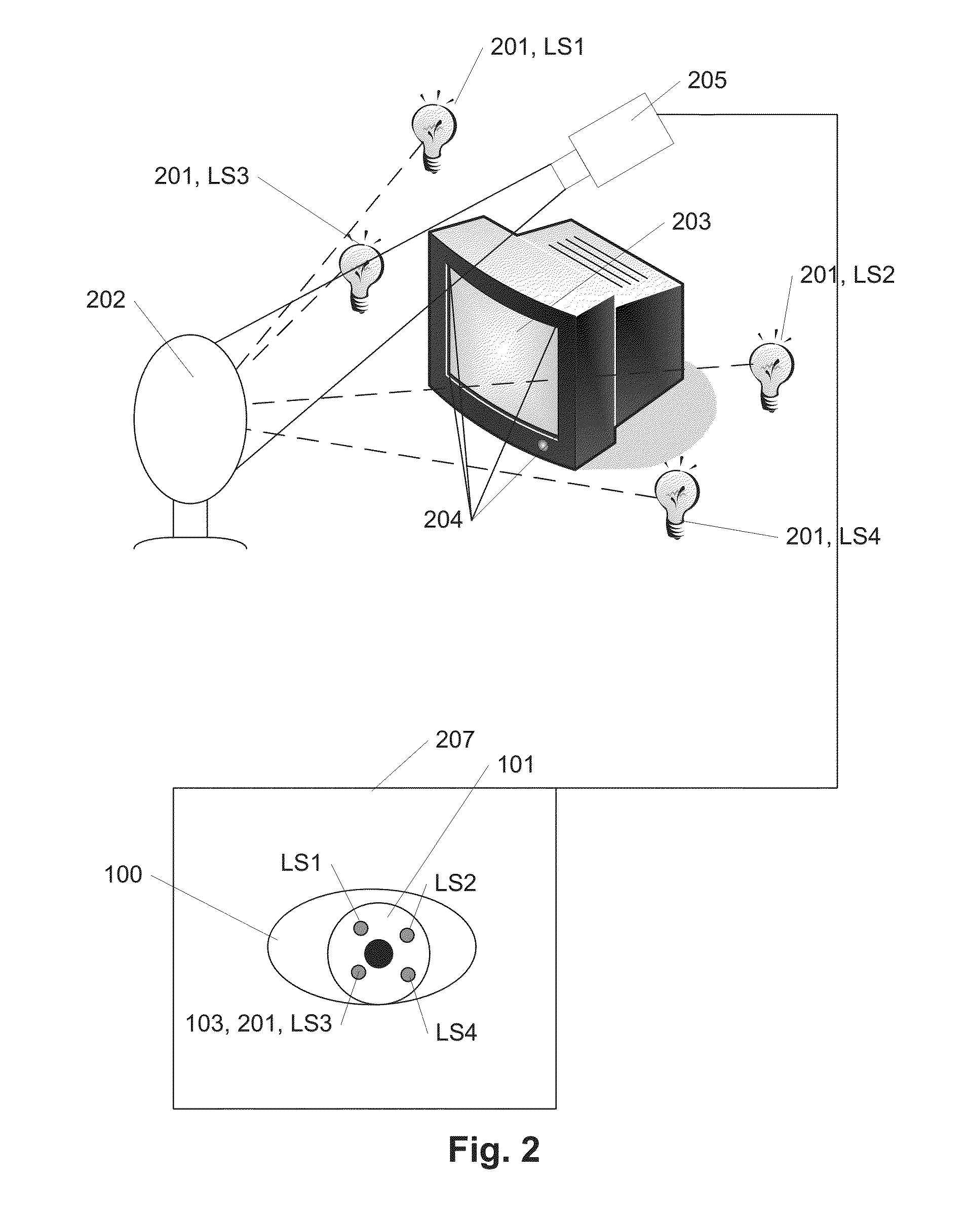
[0036]In FIG. 1 the principle behind eye gaze tracking according to the present invention is illustrated. In FIG. 1A is illustrated an eye 100 with the cornea 101 covering the central pupil 102 and the iris 104 and as seen or monitored by a camera, another person or another image detection system (not shown).

[0037]The method of eye tracking presented in the following is based on the corneal reflections 103a of a number of light sources as sketched in FIG. 1B. According to the present method, light from four different sources is projected toward the eye, and the reflections or glints 103 are detected and measured.

[0038]In this example 4 light sources are used, but in another embodiment three light sources could be used. This would though require a special normalization procedure. Normalization of data according to 3 light sources can be done when (for example) using one of the light sources as the origin and then using the ratios of the lines from the origin to the other two reflecti...


PUM


Abstract

A method of performing eye gaze tracking of at least one eye of a user, by determining the position of the center of the eye, said method comprising the steps of:detecting the position of at least three reflections on said eye,transforming said positions to spanning a normalized coordinate system spanning a frame of reference,detecting the position of said center of the eye relative to the position of said reflections and transforming this position to said normalized coordinate system,tracking the eye gaze by tracking the movement of said eye in said normalized coordinate system.Thereby calibration of a camera, such as knowledge of the exact position and zoom level of the camera, is avoided. Further, it is not necessary to know the position of light sources. This results in a much more flexible and user friendly system.

Description

FIELD OF THE INVENTION[0001]As one of the most salient features of the human face, eyes play an important role in interpreting and understanding a person's desires, needs, cognitive processes, and emotional states. The importance of eye gaze is implicitly acknowledged as it is used for inspection of our surroundings and is important in social interaction. Robust nonintrusive eye detection and tracking is therefore crucial for human computer interaction, attentive user interfaces and understanding human affective states.[0002]Eye gaze estimation and tracking are important for many applications including human attention analysis, human cognitive state analysis, gaze-based interactive user interfaces, gaze contingent graphical display, and human factors. An eye gaze tracker is a device for analyzing eye gaze movements. As the eye scans the environment or fixates on particular objects in the scene, an eye gaze tracker simultaneously localizes the eye position in the image and tracks its...

Claims


Application Information

Patent Timeline
Patent Type & Authority Patents(United States)
IPC IPC(8): G06K9/00H04N13/04G06F3/03G06F3/01G06T7/00G02B27/00A61B3/113
CPCA61B3/113G02B27/0093G06F3/011G06F3/013G06F3/0325G06K9/00604G06T7/004H04N13/0484G06T7/70H04N13/383G06V40/19
Inventor HANSEN, DAN WITZNER
Owner ITU BUSINESS DEV AS
Why Eureka
Try Eureka