
Deposition apparatus and deposition method

a technology of deposition apparatus and deposition method, which is applied in the direction of chemical vapor deposition coating, coating, plasma technique, etc., can solve the problems of high cost, inability to achieve, and inability to uniformly supply plasma power, so as to improve the throughput of the (plasma enhanced) ald process, stable and uniform supply of rf plasma power

Active Publication Date: 2016-07-26
ASM IP HLDG BV
View PDF9 Cites 0 Cited by
  • Summary
  • Abstract
  • Description
  • Claims
  • Application Information

AI Technical Summary

Benefits of technology

[0023]According to the exemplary embodiments of the present invention, it is possible to stably and uniformly supply RF plasma power to a plurality of individual reactors for a longer time than when an existing vacuum relay is used. Further, the diodes may be used to implement switching speed which is about 40 times faster than that of the existing vacuum relay, which makes it possible to improve a throughput in the (plasma enhanced) ALD process.

Problems solved by technology

Therefore, the multi-reactor chamber can achieve mass productivity and precise control over each substrate, which cannot be achieved in conventional batch-type apparatuses.
However, a plurality of RF generators and matching boxes that are used lead to high cost.
In the case of the vacuum relay, however, the plasma power may not be uniformly supplied, due to a short lifetime, frequent contact failures and the like.

Method used


Image

  • Deposition apparatus and deposition method
  • Deposition apparatus and deposition method
  • Deposition apparatus and deposition method

Examples


Embodiment Construction

[0027]The present invention will be described more fully hereinafter with reference to the accompanying drawings, in which exemplary embodiments of the invention are shown. As those skilled in the art would realize, the described embodiments may be modified in various different ways, all without departing from the spirit or scope of the present invention.

[0028]In the drawings, the thickness of layers, films, panels, regions, etc., are exaggerated for clarity. Like reference numerals designate like elements throughout the specification. It will be understood that when an element such as a layer, film, region, or substrate is referred to as being “on” another element, it can be directly on the other element or intervening elements may also be present. In contrast, when an element is referred to as being “directly on” another element, there are no intervening elements present.

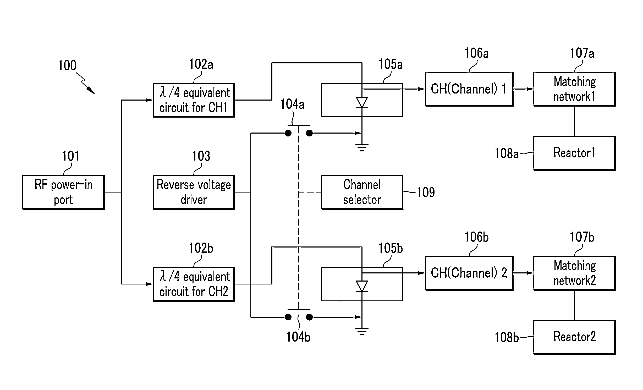
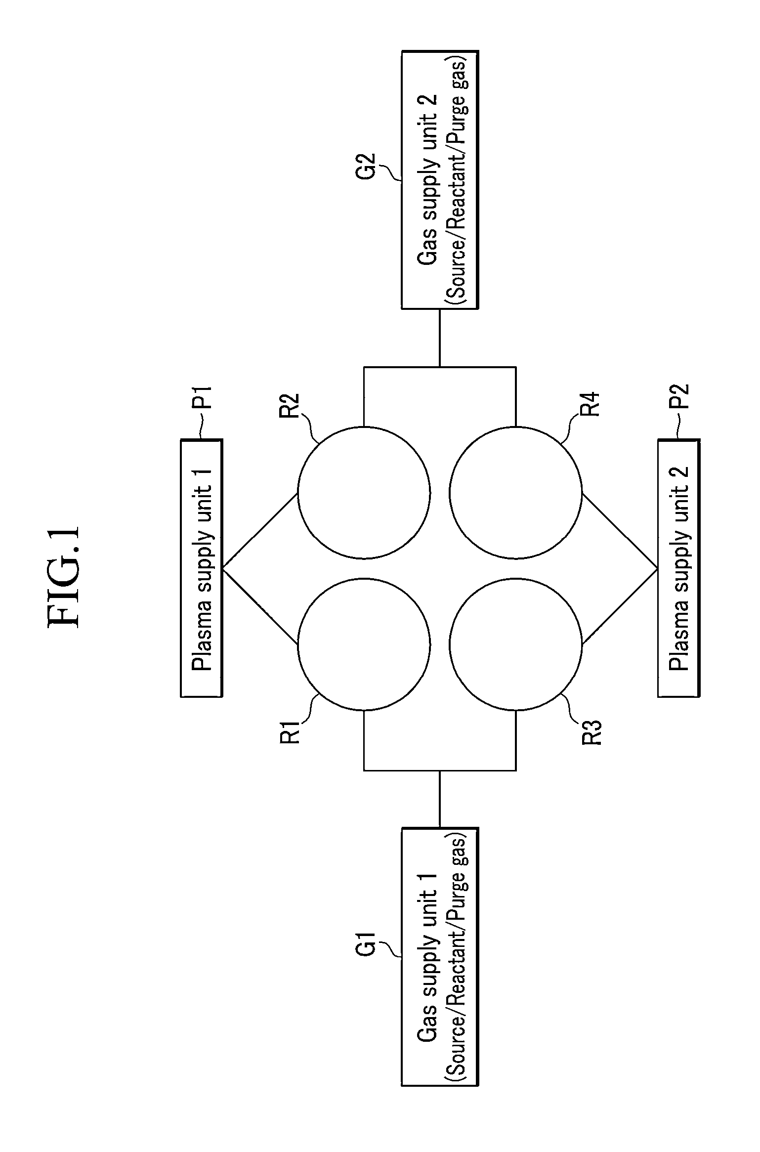
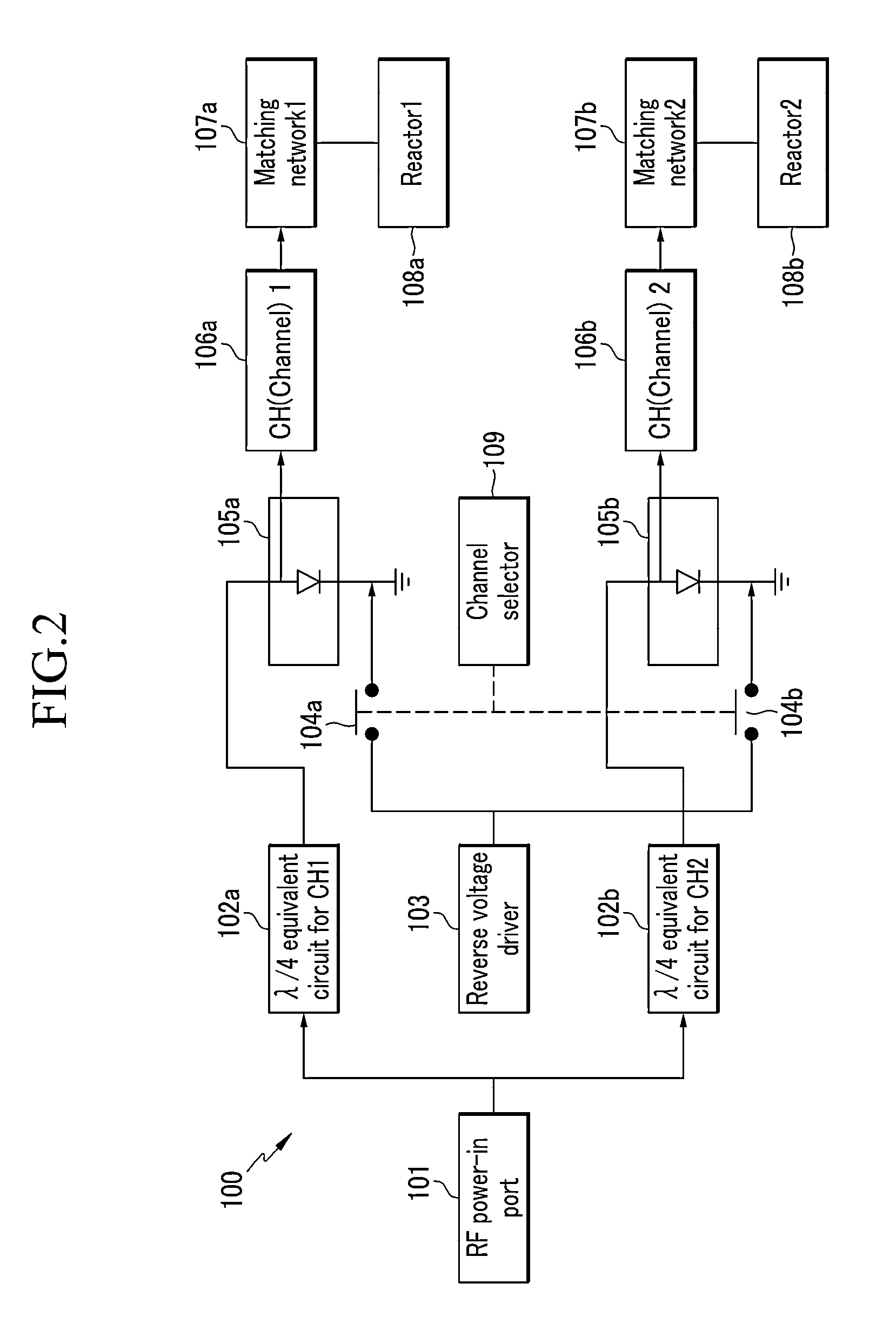
[0029]Then, referring to FIG. 1, a deposition apparatus according to an exemplary embodiment of the present inv...


PUM

PropertyMeasurementUnit
switching timeaaaaaaaaaa
reverse voltageaaaaaaaaaa

Abstract

A deposition apparatus according to an exemplary embodiment of the present invention includes a plurality of reactors; a plurality of gas supply units connected to the plurality of reactors; and a plurality of plasma supply units connected to the plurality of reactors. Each of the plasma supply units includes: a plasma power supplier; a plurality of diodes connected to the plasma power supplier; and a reverse voltage driver connected to the plurality of diodes through respectively corresponding switches.

Description

CROSS-REFERENCE TO RELATED APPLICATION[0001]This application claims priority to and the benefit of Korean Patent Application No. 10-2012-0008739 filed in the Korean Intellectual Property Office on Jan. 30, 2012, the entire contents of which are incorporated herein by reference.BACKGROUND OF THE INVENTION[0002](a) Field of the Invention[0003]The present invention relates to a deposition apparatus and a deposition method.[0004](b) Description of the Related Art[0005]Recently, many efforts have been made for mass production in a semiconductor process. Particularly, since an atomic layer deposition (ALD) process has a problem of low throughput, a variety of attempts have been made to overcome that problem. For example, a batch-type chamber was introduced in which a plurality of substrates are mounted vertically. Another type of chamber includes a plurality of single wafer processing reactors therein. In the latter case, a multi-reactor chamber developed by ASM Genitech Korea Ltd. is rel...

Claims


Application Information

Patent Timeline
Patent Type & Authority Patents(United States)
IPC IPC(8): C23C16/52C23C16/455H01J37/32
CPCC23C16/52C23C16/45536H01J37/32082H01J37/32174H01J37/32899H01L21/205C23C16/513
Inventor CHO, HYUN-KYU
Owner ASM IP HLDG BV
Learn More