Immittance conversion circuit and filter
a conversion circuit and filter technology, applied in the field of bidirectional circuits, can solve the problems of loss, performance and the range of use of the circuit, and adversely affect the function value generated at the function generation terminal,
- Summary
- Abstract
- Description
- Claims
- Application Information
AI Technical Summary
Benefits of technology
Problems solved by technology
Method used
Image
Examples
embodiment 1
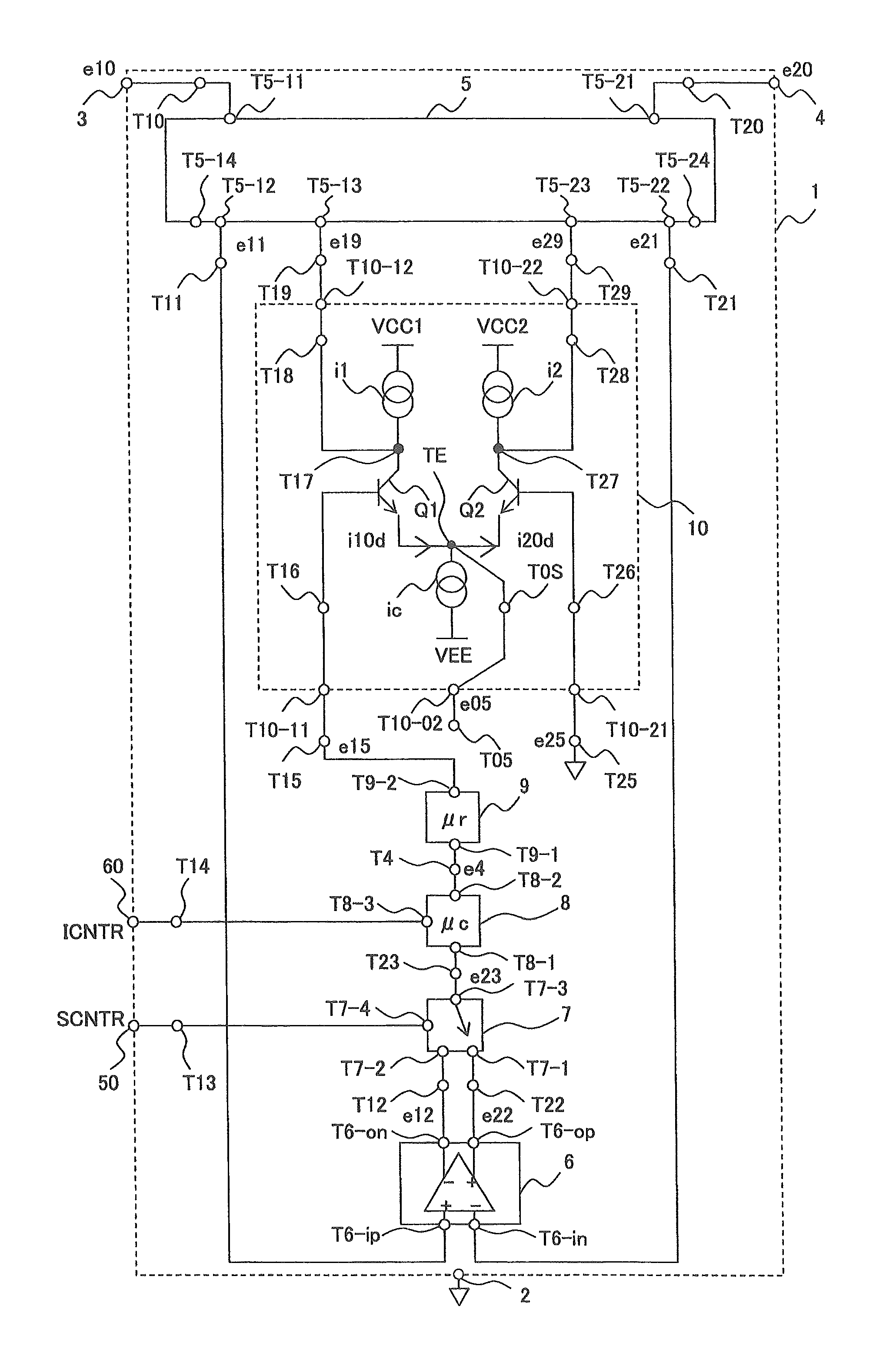
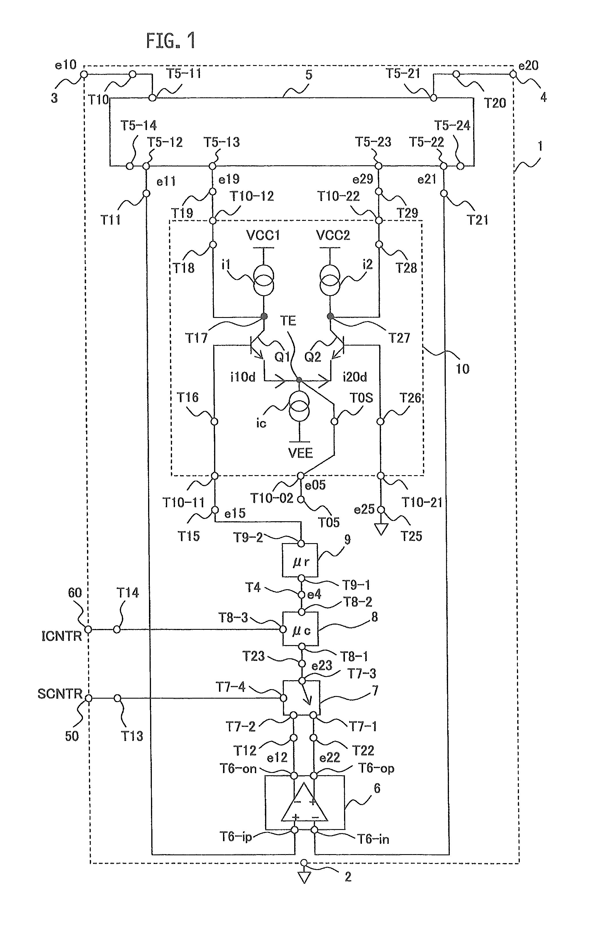
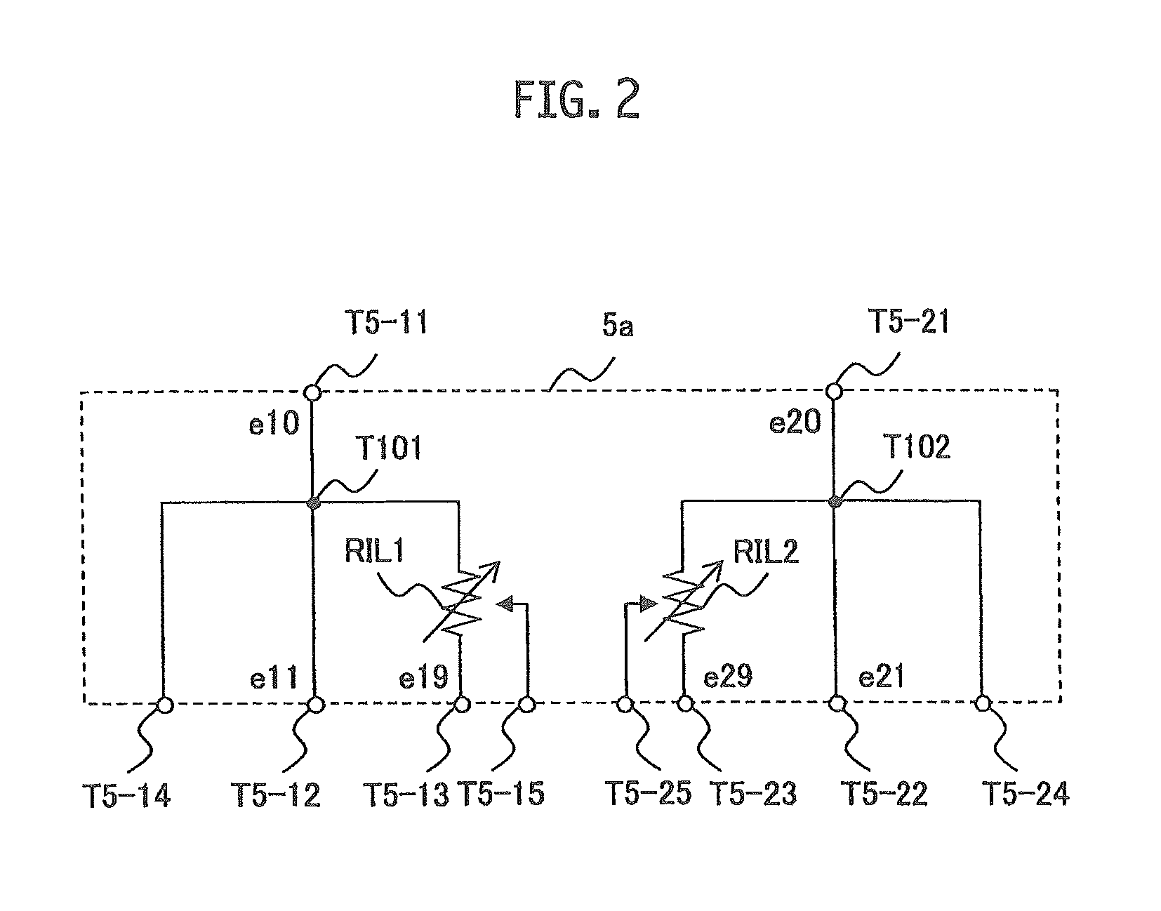
[0044]In the first embodiment, with reference to FIG. 1, detailed description is given of the example of using the impedance conversion generation circuit 5a shown in FIG. 2 as the immittance conversion generation circuit 5 included in the bidirectional floating immittance conversion circuit 1. In the first embodiment, the circuit shown in FIG. 3 is used as the conversion target circuit 9.
[0045]The bidirectional floating immittance conversion circuit 1 includes a reference terminal 2, a first terminal 3, a second terminal 4, a sign switching control input terminal 50, an immittance level control input terminal 60, the immittance conversion generation circuit 5, a difference signal detection circuit 6, a signal sign switching circuit 7, the conversion target circuit (origin circuit) 9, and an immittance conversion drive circuit 10.
[0046]The immittance conversion generation circuit 5 divides a signal e10 inputted to a terminal T5-11 through a terminal T10 from the first terminal 3, an...
embodiment 2
[0142]In the first embodiment, the description is given of the case where the conditions of Formula (3) are satisfied when the value of the total gain μta is large. Ina second embodiment, description is given of a bidirectional floating immittance conversion circuit 1 in the case where the value of the total gain μta extensively changes, i.e., a correspondence relationship between the two-terminal impedance z0 and the total gain μta of the conversion target circuit always includes the same constant term element for all elements in the coefficient matrix on the right-hand side of Formula (2) even if the value of the total gain μta is small.
[0143]In order to achieve such an effect, a predetermined correction signal from a signal correction circuit (also called an immittance conversion control circuit) shown in FIG. 8 is supplied to the terminal T10-21 in the bidirectional floating immittance conversion circuit 1 shown in FIG. 1. As a result, the floating effect of the immittance conve...
embodiment 3
[0198]In a third embodiment, description is given of means for reducing unintended resistance components (loss) in the bidirectional floating immittance conversion circuit 1.
[0199]For example, in the case of aiming for a high resonance acutance (high Q value) as the total gain μta, unintended loss needs to be reduced. Also, for example, when reactance values are set for the first and second immittance level setting impedance elements RIL1 and RIL2, unintended loss needs to be reduced to realize pure reactance values.
[0200]In this case, a change is made also including the constant term ½ in the denominator on the right-hand side of Formula (9). In order to do this, a loss control circuit 21 may be added to the circuit shown in FIG. 1.
[0201]A method for adding the loss control circuit 21 is described using the loss compensation circuit 20 shown in FIG. 10. The loss compensation circuit 20 includes terminals T20-11, T20-21, T20-12, T20-22, T20-3, T20-4, T20-5 and T20-6. These eight ter...
PUM
 Abstract
Description
Claims
Application Information
 - R&D
- Intellectual Property
- Life Sciences
- Materials
- Tech Scout
- Unparalleled Data Quality
- Higher Quality Content
- 60% Fewer Hallucinations
Browse by: Latest US Patents, China's latest patents, Technical Efficacy Thesaurus, Application Domain, Technology Topic, Popular Technical Reports.
© 2025 PatSnap. All rights reserved.Legal|Privacy policy|Modern Slavery Act Transparency Statement|Sitemap|About US| Contact US: help@patsnap.com


