Automatic calibration circuits for operational calibration of critical-path time delays in adaptive clock distribution systems, and related methods and systems

a time delay and automatic calibration technology, applied in the field of automatic calibration circuits, can solve the problems of inefficiently expending additional power, affecting the performance and energy efficiency of powered circuits, and affecting the accuracy of adaptive clock distribution systems, so as to reduce calibration time and overhead, reduce delay variations, and reduce calibration time.

Active Publication Date: 2016-08-09
QUALCOMM INC
View PDF13 Cites 22 Cited by
  • Summary
  • Abstract
  • Description
  • Claims
  • Application Information

AI Technical Summary

Benefits of technology

[0010]In additional aspects disclosed herein, an automatic calibration circuit is also provided in the adaptive clock distribution system. The automated calibration circuit is configured to calibrate the tunable delay paths in the dynamic variation monitor based on operational conditions (e.g., operating frequency and voltage) and environmental conditions (e.g., temperature) of the clocked circuit. For example, the automated calibration circuit may be configured to calibrate the tunable delay paths in the dynamic variation monitor based on operational conditions during in-field operation. By providing the automatic calibration circuit in the adaptive clock distribution system to provide operational calibration of the dynamic variation monitor, costly calibration time and overhead incurred with calibrating each adaptive clock distribution system during test over a wide range of operational and environmental conditions, or over a limited range of operational and environmental conditions during test to reduce calibration time, can be reduced or avoided.
[0011]Calibrating the tunable delay paths in the dynamic variation monitor reduces delay variations between critical-path delay timings in the clocked circuit and the tunable delay paths in the dynamic variation monitor without reducing accuracy in the dynamic variation monitor detecting the on-set of a voltage droop based on timing transitions in a tunable delay path. Reducing delay variations between the critical-path delay timings in the clocked circuit and the tunable delay paths in the dynamic variation monitor allows the additional timing margin in the dynamic variation monitor to be reduced. Reducing the additional timing margin in the dynamic variation monitor increases the magnitude of the voltage droop mitigated by the adaptive clock distribution system, which increases throughput of the clocked circuit. Reducing the additional timing margin in the dynamic variation monitor to improve the effectiveness of the adaptive clock distribution system can also reduce energy consumption, because tasks will be completed faster by the clocked circuit due to the increased throughput of the clocked circuit.

Problems solved by technology

High-frequency voltage droops may result in the largest power supply voltage magnitude change, and thus have a severe impact on powered circuit performance and energy efficiency.
If for example, the CPU executes back-to-back complex instructions (e.g., hardware multiplies), current consumption may quickly change at about one (1) amp (A) per nanosecond (ns), thereby causing a power supply voltage droop.
However, since voltage droops events do not occur frequently, additional power is provided by the power supply to the powered circuit than what is required for the powered circuit to function properly during non-voltage droop times, thus inefficiently expending additional power.
However, providing for a powered circuit to operate at a reduced performance level to compensate for infrequent power supply voltage droops may also be undesired.

Method used


Image

  • Automatic calibration circuits for operational calibration of critical-path time delays in adaptive clock distribution systems, and related methods and systems
  • Automatic calibration circuits for operational calibration of critical-path time delays in adaptive clock distribution systems, and related methods and systems
  • Automatic calibration circuits for operational calibration of critical-path time delays in adaptive clock distribution systems, and related methods and systems

Examples


Embodiment Construction

[0025]With reference now to the drawing figures, several exemplary aspects of the present disclosure are described. The word “exemplary” is used herein to mean “serving as an example, instance, or illustration.” Any aspect described herein as “exemplary” is not necessarily to be construed as preferred or advantageous over other aspects.

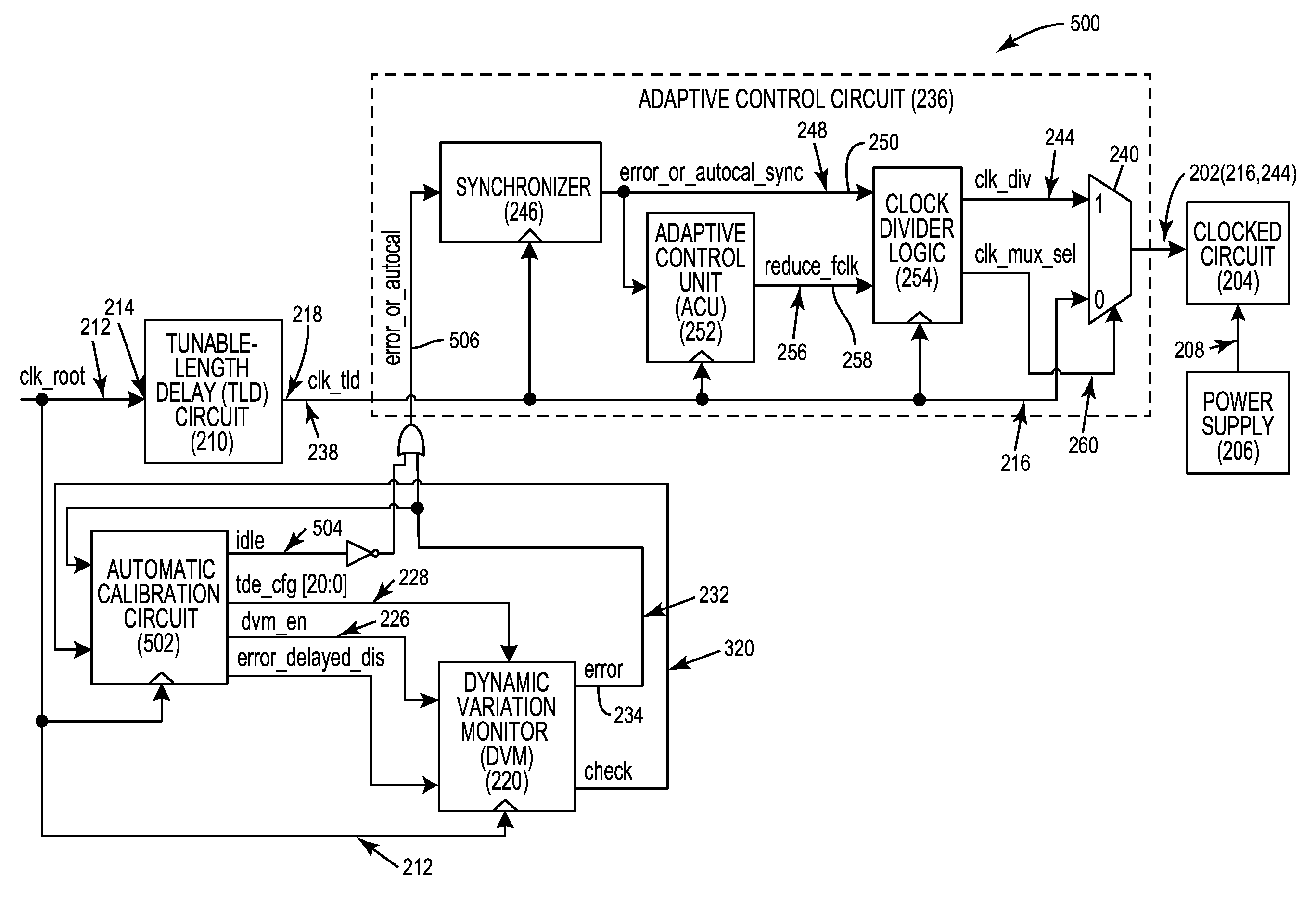
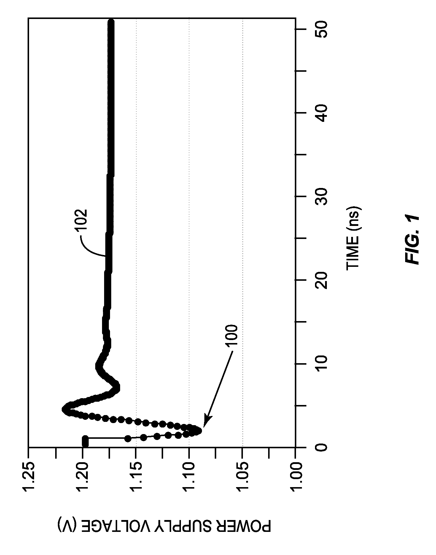
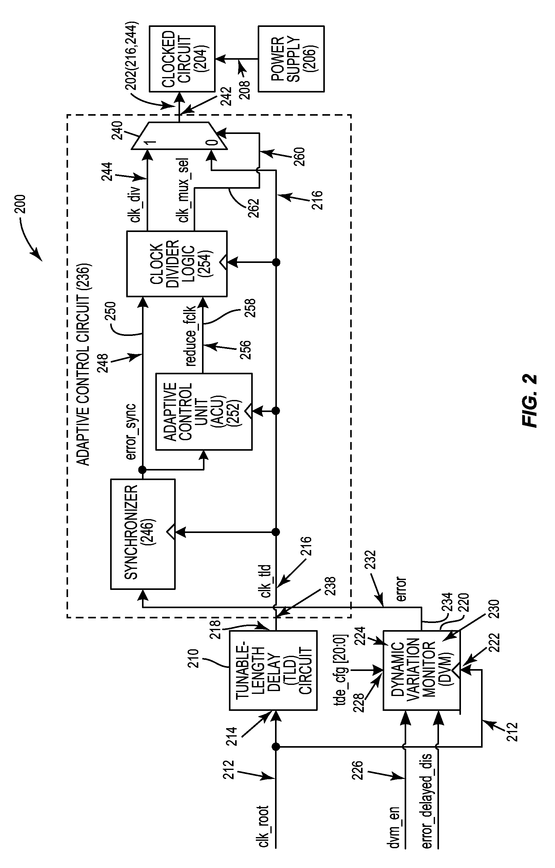
[0026]Aspects disclosed in the detailed description include automatic calibration circuits for operational calibration of critical-path time delays in adaptive clock distribution systems. Related methods and systems are also disclosed. In one aspect, an adaptive clock distribution system is provided that receives a clock signal to be distributed to clocked circuits. The adaptive clock distribution system includes a tunable-length delay circuit. The tunable-length delay circuit is configured to delay distribution of the clock signal provided to a clocked circuit. Delaying distribution of the clock signal provides a response time for detecting the volta...


PUM


Abstract

Automatic calibration circuits for operational calibration of critical-path time delays in adaptive clock distribution systems, and related methods and systems, are disclosed. The adaptive clock distribution system includes a tunable-length delay circuit to delay distribution of a clock signal provided to a clocked circuit, to prevent timing margin degradation of the clocked circuit after a voltage droop occurs in a power supply supplying power to the clocked circuit. The adaptive clock distribution system also includes a dynamic variation monitor to reduce frequency of the delayed clock signal provided to the clocked circuit in response to the voltage droop in the power supply, so that the clocked circuit is not clocked beyond its performance limits during a voltage droop. An automatic calibration circuit is provided in the adaptive clock distribution system to calibrate the dynamic variation monitor during operation based on operational conditions and environmental conditions of the clocked circuit.

Description

PRIORITY APPLICATION[0001]The present application claims priority to U.S. Provisional Patent Application Ser. No. 62 / 047,278 filed on Sep. 8, 2014 and entitled “AUTOMATIC CALIBRATION CIRCUITS FOR IN-FIELD, OPERATIONAL CALIBRATION OF CRITICAL-PATH TIME DELAYS IN ADAPTIVE CLOCK DISTRIBUTION SYSTEMS, AND RELATED METHODS AND SYSTEMS,” the contents of which is incorporated herein in its entirety.BACKGROUND[0002]I. Field of the Disclosure[0003]The technology of the disclosure relates generally to monitoring circuits for monitoring a power supply to determine if a power supply voltage has drooped, and adaptively changing the performance of a powered circuit powered by the power supply in response to compensate for the voltage droop.[0004]II. Background[0005]Circuits such as central processing units (CPUs) or digital signal processors (DSPs) require power to operate. In this regard, a power supply provides a supply voltage to a powered circuit. During normal operation of a circuit, a power ...

Claims


Application Information

Patent Timeline
Patent Type & Authority Patents(United States)
IPC IPC(8): H03H11/26H03K5/13G06F1/10H03K5/156H03K5/134H03K5/00
CPCH03K5/13G06F1/10H03K5/156H03K5/134H03K2005/00019
Inventor BOWMAN, KEITH ALANBRIDGES, JEFFREY TODDRAINA, SARTHAKKOLLA, YESHWANT NAGARAJJEONG, JIHOONATALLAH, FRANCOIS IBRAHIMFLEDERBACH, WILLIAM ROBERTFISCHER, JEFFREY HERBERT
Owner QUALCOMM INC
Why Eureka
Try Eureka