Method for clock calibration

a clock signal and clock technology, applied in the field of integrated circuits, can solve problems such as delay and complexity in the design

Active Publication Date: 2016-08-09
APPLE INC
View PDF9 Cites 27 Cited by
  • Summary
  • Abstract
  • Description
  • Claims
  • Application Information

AI Technical Summary

Problems solved by technology

Distributing a single clock signal across multiple voltage domains may result in level shifting circuits being used to cross voltage domains, which may introduce delay and complexity into the design.

Method used


Image

  • Method for clock calibration
  • Method for clock calibration
  • Method for clock calibration

Examples


Embodiment Construction

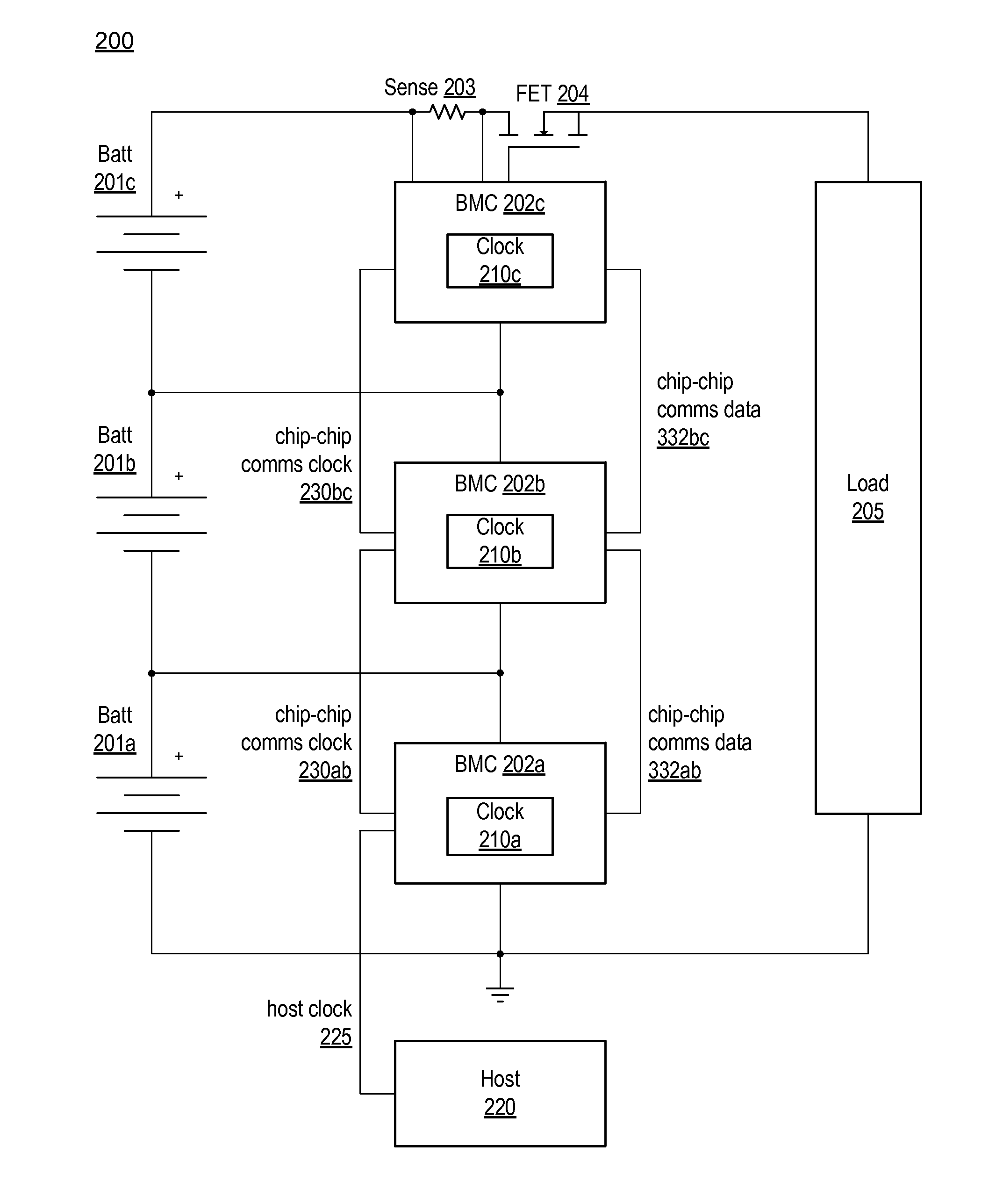
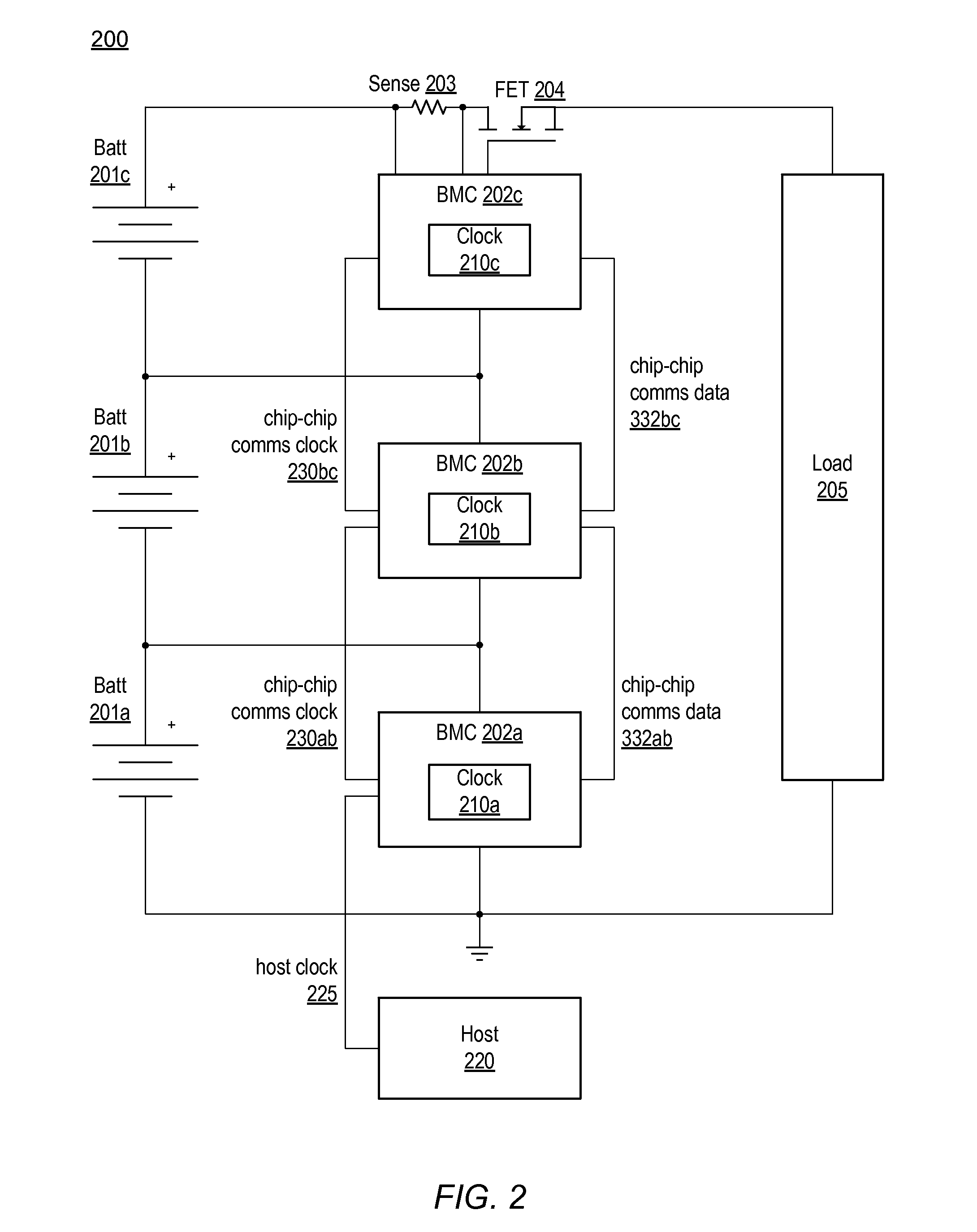
[0007]Various embodiments of a communication circuit are disclosed. Broadly speaking, a system, an apparatus, and a method are contemplated in which the system may include a plurality of devices, wherein each device of the plurality of devices has a respective clock source. A first device of the plurality of devices may be configured to generate a first clock signal. A second device of the plurality of devices may be configured to generate a second clock signal, receive the first clock signal from the first device, and modify a first frequency of the first clock signal. The second device may be further configured to adjust a second frequency of the second clock signal dependent upon the modified first frequency of the first clock signal.

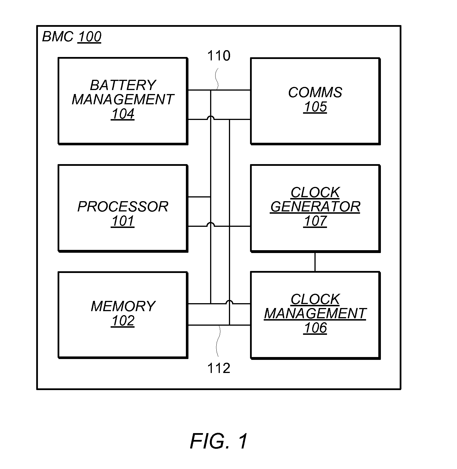
[0008]In a further embodiment, the first device may be further configured to use a clock output of an inter-integrated circuit (I2C) interface to generate the first clock signal. In another embodiment, to modify the first frequency of the first clock...


PUM


Abstract

A system may include a plurality of devices, wherein each device of the plurality of devices has a respective clock source. A first device of the plurality of devices may be configured to generate a first clock signal. A second device of the plurality of devices may be configured to generate a second clock signal, receive the first clock signal from the first device, and modify a first frequency of the first clock signal. The second device may be further configured to adjust a second frequency of the second clock signal dependent upon the modified first frequency of the first clock signal.

Description

PRIORITY CLAIM[0001]The present application claims benefit of priority to U.S. Provisional Application No. 62 / 096,323, filed on Dec. 23, 2014, which is hereby incorporated by reference in its entirety as though fully and completely set forth herein. In the event any statements seemingly conflict, then the statements disclosed in the present application supersede the conflicting statements disclosed in U.S. Provisional Application No. 62 / 096,323.BACKGROUND[0002]1. Technical Field[0003]Embodiments described herein are related to the field of integrated circuits, and more particularly to calibrating clock signals between integrated circuits.[0004]2. Description of the Related Art[0005]Computing systems may include one or more systems-on-a-chip (SoCs), which may integrate a number of different functions, such as, application execution, graphics processing and audio processing, onto a single integrated circuit (IC). With numerous functions included in a single IC, chip count may be kept ...

Claims


Application Information

Patent Timeline
Patent Type & Authority Patents(United States)
IPC IPC(8): H03K5/135H03L7/00
CPCG01R31/3675H02J7/0052H02J7/007G01R31/3655H02J7/0068H03K19/017509H03L7/00H02J7/0026H02J2007/0059G06F13/4256H02J7/0021H01M10/48Y02D10/00Y02E60/10G01R31/374H02J7/0029H02J7/0013H02J2207/20H02J7/00
Inventor STIRK, GARY L.
Owner APPLE INC
Why Eureka
Try Eureka