
Devices and methods for knee replacement

a knee replacement and device technology, applied in the field of patient-specific knee replacement devices, can solve the problems of pain, loosening of prostheses or accelerating wear, untoward pain or premature wear of bearing surfaces, and repairing improperly sized prosthetic components may require additional surgeries

Inactive Publication Date: 2016-08-16
BULLSEYE HIP REPLACEMENT
View PDF30 Cites 22 Cited by
  • Summary
  • Abstract
  • Description
  • Claims
  • Application Information

AI Technical Summary

Benefits of technology

This approach enhances the accuracy of bone resection and prosthetic placement, reducing the risk of malalignment and premature wear, thereby minimizing the need for secondary surgeries and improving the longevity of the joint replacement.

Problems solved by technology

Additionally, malposition of joint replacement prosthetics can result in untoward pain or premature wear of the bearing surfaces, which may require additional surgeries to correct.
Improperly sized prosthetic components that are tool large or too small may also cause pain, loosening of prostheses or accelerated wear.
Repairing improperly sized prosthetic components may require additional surgeries.
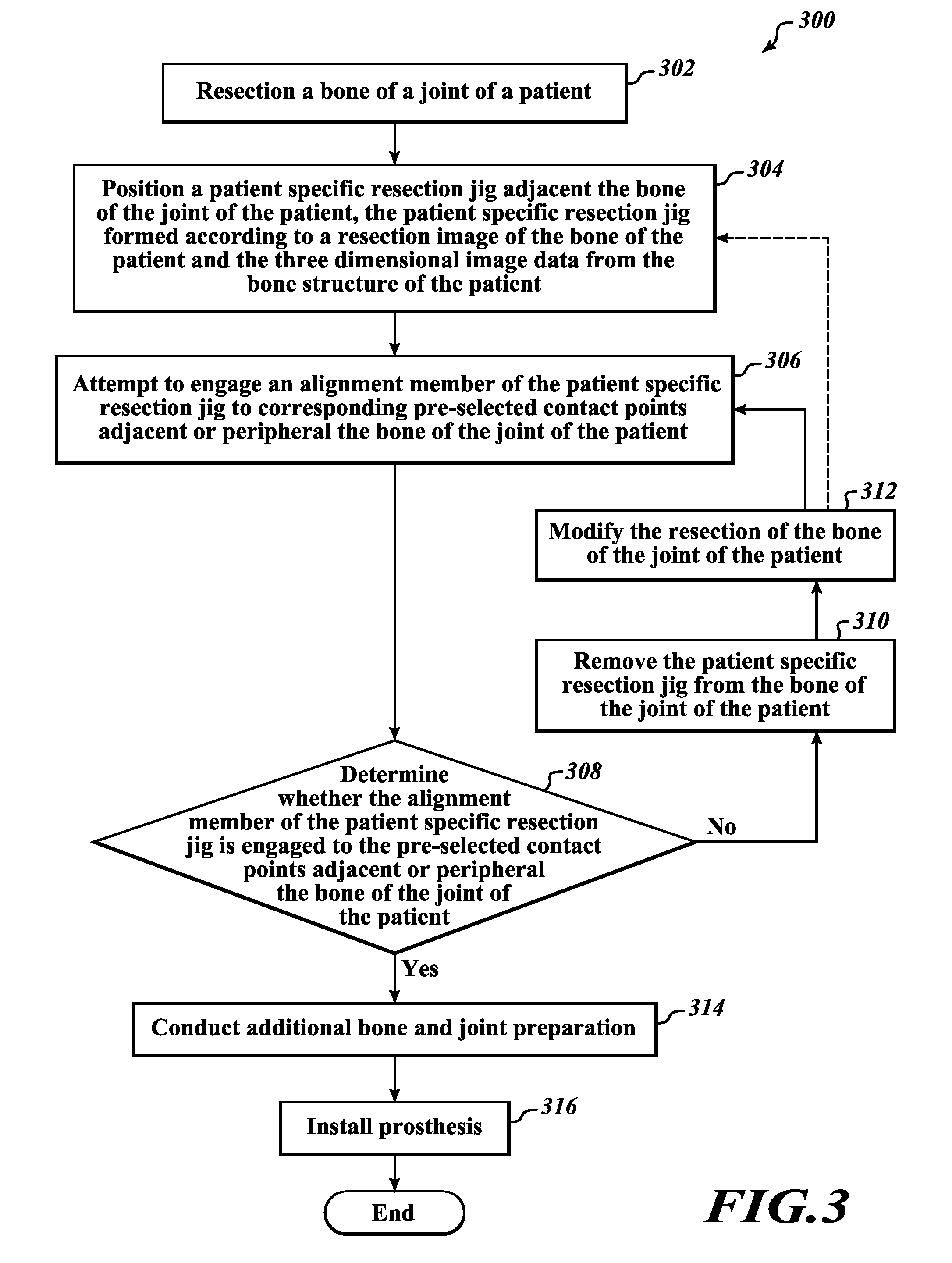
One concern during the bone removal stage of a knee replacement surgery is that the surgeon may not make the correct cuts to the bones which may result in malaligned prosthesis and a poorly functioning knee replacement.
Both improper bone cuts and improper sized implants may lead to untoward pain, early wear, or early loosening of prostheses that may result in a secondary unnecessary surgery.
Some surgeons use guides or generic extramedullary or intramedullary cutting guides during surgery in an attempt to properly place the prosthetics; however, accuracy and simplicity of existing devices and methods remain limited due to a variety of factors.

Method used


Image

  • Devices and methods for knee replacement
  • Devices and methods for knee replacement
  • Devices and methods for knee replacement

Examples


Embodiment Construction

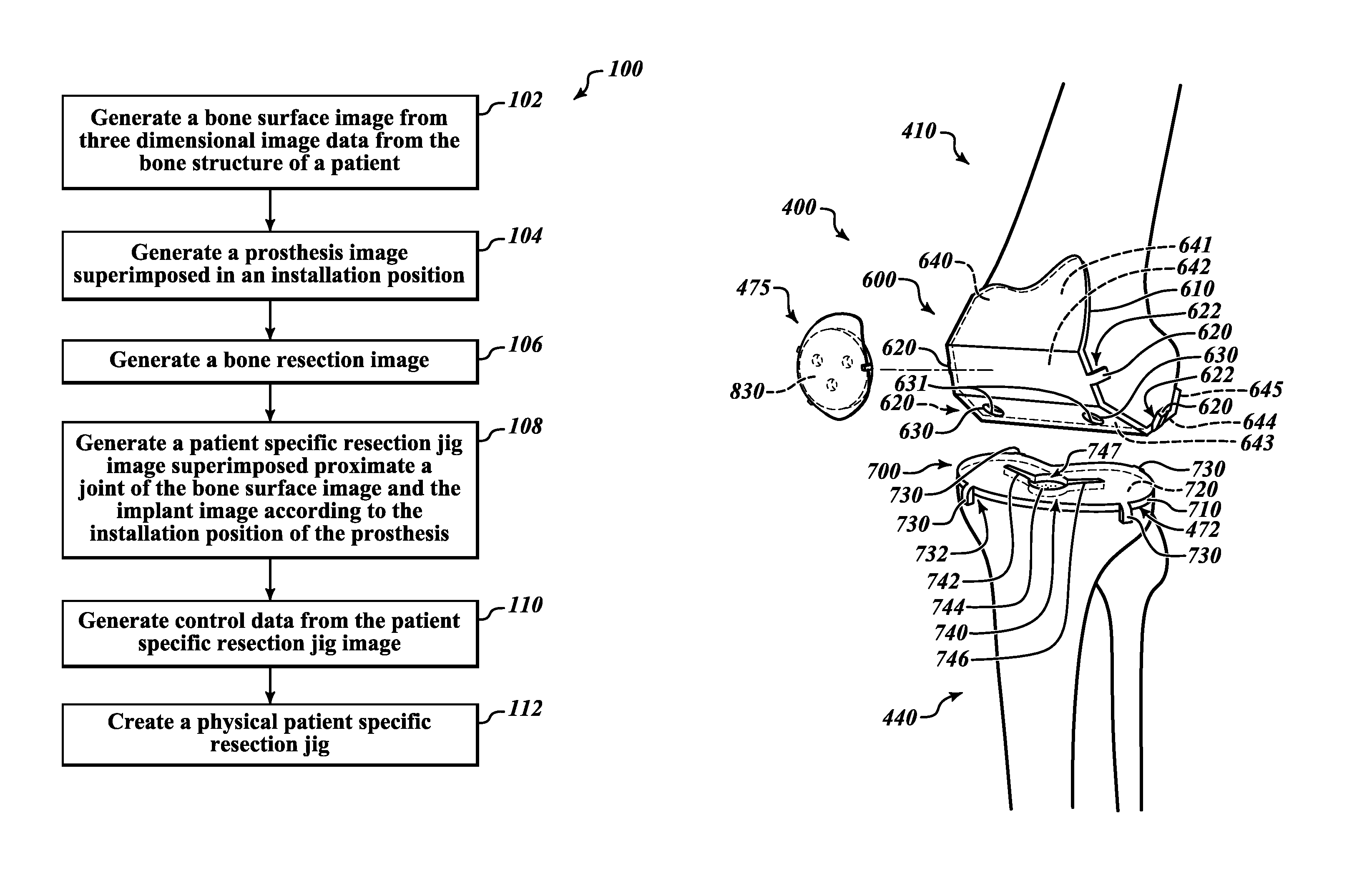
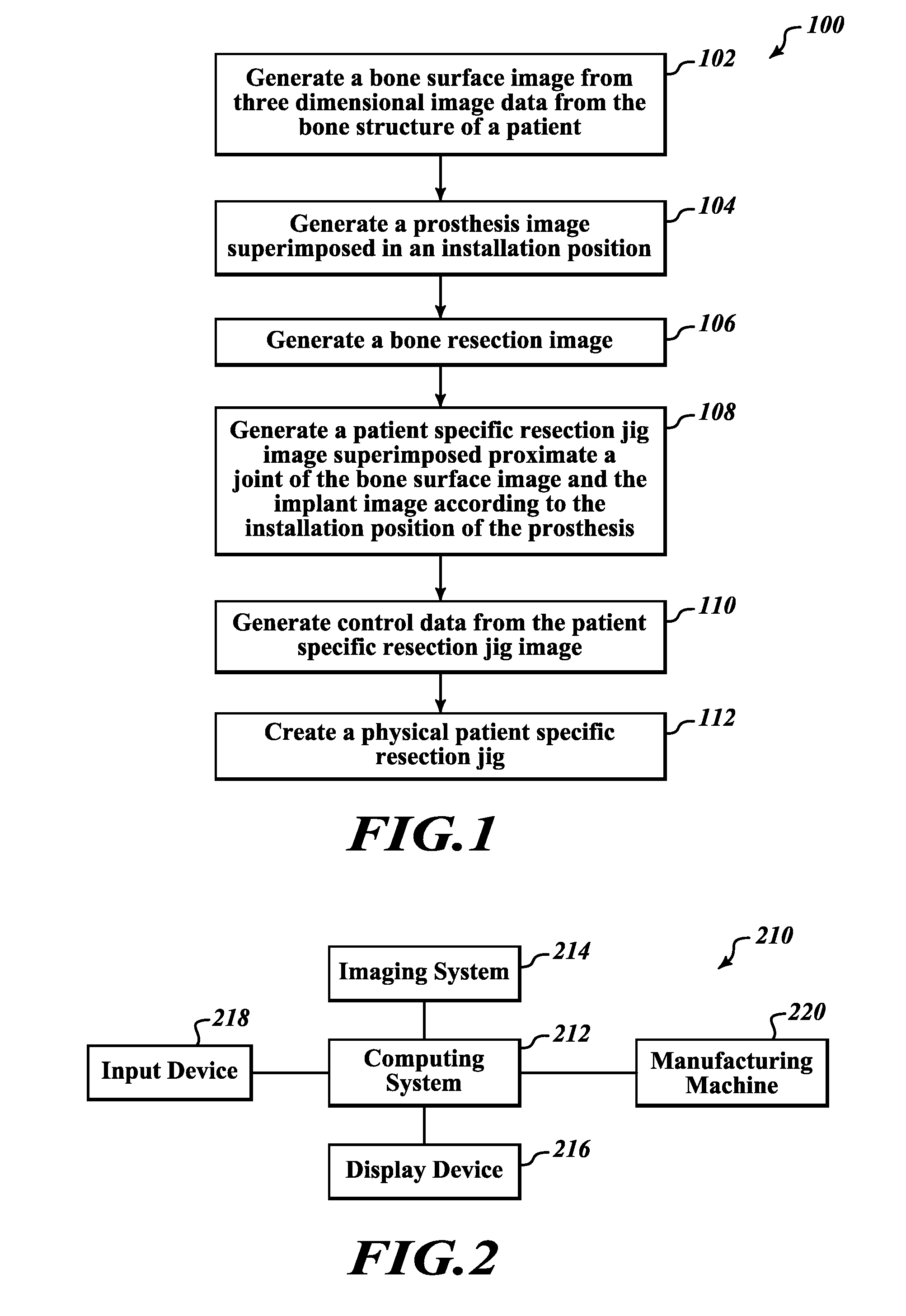
[0024]The present disclosure pertains to patient-specific knee replacement devices and methods of designing, manufacturing, and using such devices for achieving accurate component or prosthesis sizing and placement during knee replacement surgery based on computer generated imaging of a particular patient. When an orthopedic surgeon recommends knee replacement surgery for a particular patient, a variety of images may be obtained utilizing CT, MRI, and other scans, such as x-rays, to generate 3D modeling of the patient's bone structure, particularly the femur, the tibia, and then patella. From such 3D models, the surgeon may determine the specific, final size, geometry, location, and orientation of the femoral component, tibial component, and patellar components to be secured to the patient's bones during surgery. Surgeons may select the prosthetics from a number of standard sizes and shapes or may use patient-specific prosthetics.

[0025]Once the final size, geometry, location, and or...


PUM


Abstract

A device for use in joint replacement surgery is disclosed, the device may comprise a patient-specific jig having a body formed using three dimensional data corresponding to a first resection surface of a bone of a patient according to a preoperative plan. The body may also include a first bone facing surface configured to match the first resection surface of the bone of the patient according to the three dimensional data and an alignment perimeter sized and shaped to match a perimeter of the resection surface of the bone of the patient according to the three dimensional data.

Description

BACKGROUND[0001]1. Technical Field[0002]The present disclosure relates to devices and methods for the replacement of joints, and more particularly, to patient-specific knee replacement devices, including methods of manufacturing and using such devices for achieving accurate resection of patient bones and accurate placement of prosthetics based on computer generated imaging of a patient.[0003]2. Background of the Invention[0004]One known method of treating knee and other joints with arthritis and other medical conditions is to replace surfaces of articulating joints with prosthetic devices through surgical procedures. It is critical that such prosthetic devices are accurately designed and manufactured and that they are installed correctly so that they relieve pain and provide an effective treatment method for such ailments. An orthopedic surgeon performing such joint replacement on a patient seeks to ensure, through surgery, adequate placement of the prosthetic and proper reconstruct...

Claims


Application Information

Patent Timeline
Patent Type & Authority Patents(United States)
IPC IPC(8): A61B17/15A61B17/17G05B19/4097A61B17/56A61B17/00
CPCA61B17/154A61B17/157A61B17/158G05B19/4097A61B17/155A61B17/1764G05B2219/35012A61B2017/00526A61B2034/108A61B17/1767A61B2017/568A61B34/10
Inventor GILLMAN, MICHAELGILLMAN, BENJAMIN A.
Owner BULLSEYE HIP REPLACEMENT
Learn More