Fluid pump having a radially compressible rotor

a fluid pump and rotor technology, applied in the field of mechanical engineering, can solve the problems of difficult realization of complex constructions of such pumps, and difficulty in operating reliably with the desired service life, and achieve the effects of simple construction design, reliable pump function, and low cos

Active Publication Date: 2016-08-16
ECP ENTWICKLUNGSGMBH
View PDF256 Cites 33 Cited by
  • Summary
  • Abstract
  • Description
  • Claims
  • Application Information

AI Technical Summary

Benefits of technology

[0012]It is therefore the underlying object of the present invention against this background to provide a fluid pump of the initially named kind whi...

Problems solved by technology

Experience has shown that complex constructions for such pumps are also difficult to r...

Method used


Image

  • Fluid pump having a radially compressible rotor
  • Fluid pump having a radially compressible rotor
  • Fluid pump having a radially compressible rotor

Examples


Embodiment Construction

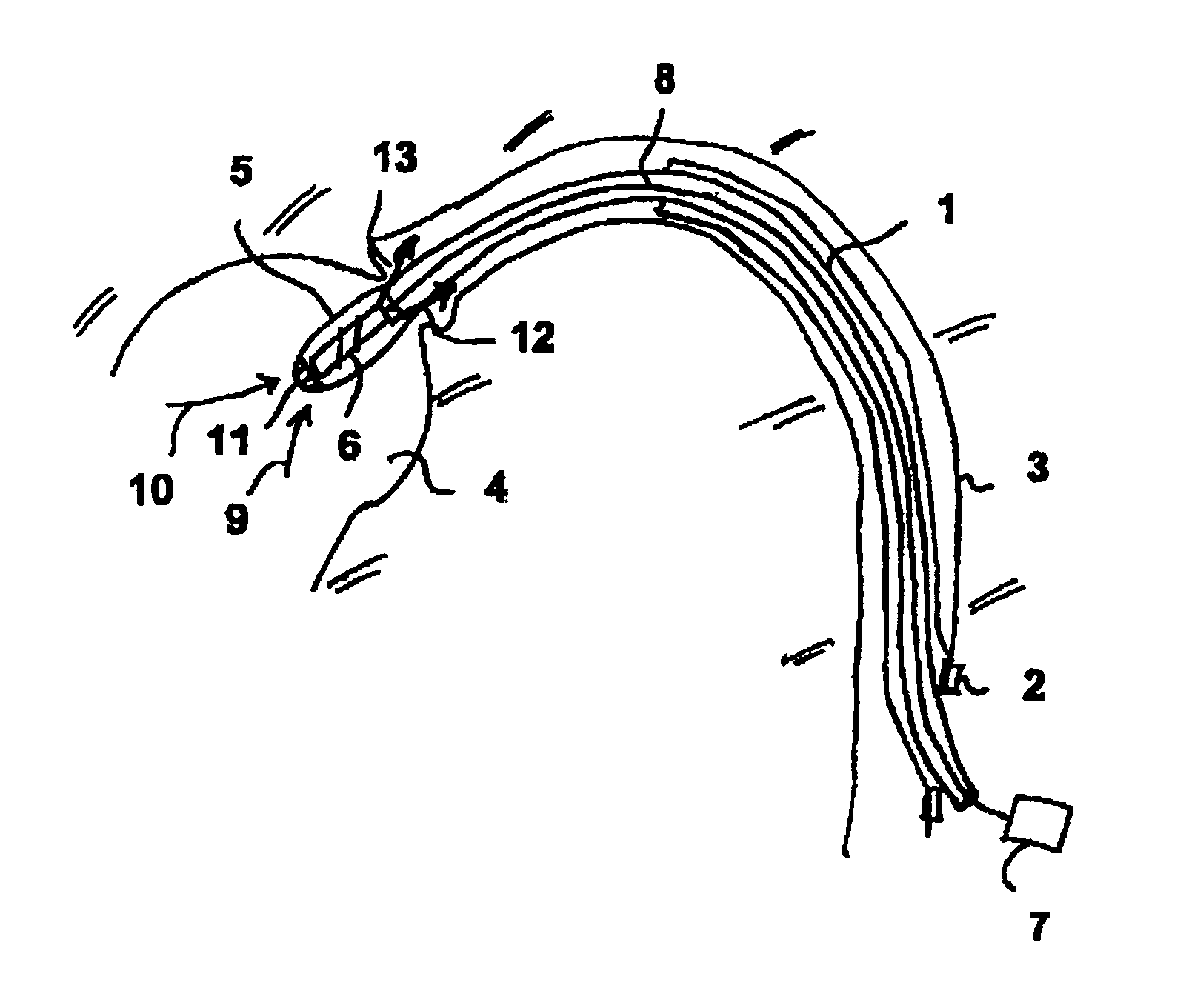
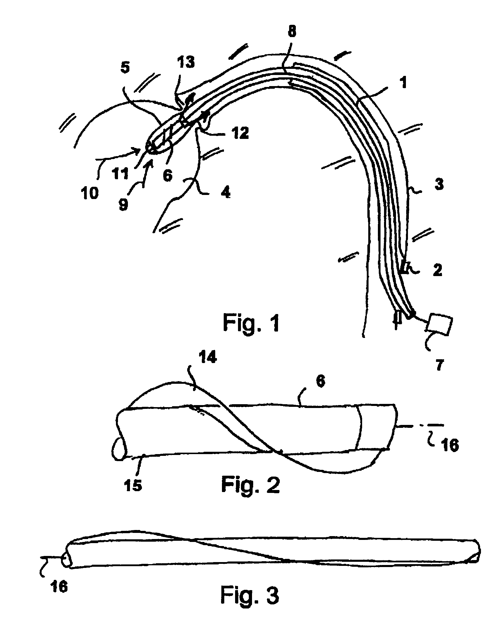
[0046]FIG. 1 shows a hollow catheter 1 which is introduced through a sluice 2 into a blood vessel 3 of a human body and which is inserted there up to the ventricle 4. At the distal end of the hollow catheter 1, a pump 5 is fastened having a rotor 6 which rotates about its longitudinal axis and thus conveys blood axially out of the ventricle 4 into the blood vessel 3.

[0047]The rotor is for this purpose drivable by a motor 7 via a shaft 8 at a high speed, typically between 10,000 and 50,000 revolutions per minute.

[0048]Blood is sucked in axially by the rotation of the rotor 6 in the direction of the arrows 9, 10 through the intake openings 11 of the pump and is expelled again in the direction of the arrows 12, 13 within the blood vessel 3. The activity of the heart in the conveying of blood is thereby replaced or supplemented.

[0049]The pump 5 has a housing surrounding the rotor 6 and is radially compressible as a whole with respect to the diameter for insertion into the blood vessel 3...


PUM


Abstract

To design the rotor as compressible in the radial direction in a fluid pump, in particular for microinvasive medical use, said rotor is configured as stretchable in its longitudinal direction by push elements and pull elements acting axially on it. A fluid pump is presented herein having a drivable rotor which is rotatable about its longitudinal axis and which has at least one impeller blade. The rotor at least partly comprises an elastically compressible and expandable material and is elastically stretchable by elements acting axially on it in the direction of its longitudinal axis. A push element and a pull element engage at different ends of the rotor and/or of a housing of the fluid pump. The push element and the pull element are configured to apply tension to the rotor by applying force in mutually opposite directions at the different ends of the rotor.

Description

BACKGROUND OF THE INVENTION[0001]The invention is in the field of mechanical engineering, in particular of micromechanics, and specifically relates to fluid pumps having a rotor and at least one impeller blade for the predominantly axial conveying of a fluid.[0002]Pumps of this kind can be used in different technical fields, particularly where deployment locations are difficult to access and a compressible rotor can be brought onto site in compressed form and can there be expanded for efficient operation.[0003]A particularly advantageous application is in the field of medicine where pumps of this kind can be introduced in particularly small construction into the body of a patient, for example through blood vessels, can be expanded at the deployment location, preferably in a ventricle, and can be operated there.[0004]To remove the pump, it can usually be compressed again and removed through a sluice.[0005]Corresponding compressible pumps are already known in different constructions.[...

Claims


Application Information

Patent Timeline
IPC IPC(8): A61M1/10F04D3/00F04D29/24A61M1/12F04D29/18A61M60/13A61M60/174A61M60/237A61M60/414A61M60/808A61M60/825
CPCA61M1/101F04D3/00F04D29/18F04D29/247A61M1/1024A61M1/125A61M60/414A61M60/148A61M60/808A61M60/174A61M60/237A61M60/13A61M60/825A61M60/135A61M60/818A61M60/205F04D3/02F04D29/026F04D29/043F04D29/046F04D29/181F04D29/528
Inventor TOELLNER, THOMAS
Owner ECP ENTWICKLUNGSGMBH
Why Eureka
Try Eureka