
Output driver having output impedance adaptable to supply voltage and method of use

a technology of output driver and input voltage, which is applied in the direction of pulse generator, pulse technique, electric pulse generator details, etc., can solve the problems of limiting the high-speed i/o performance of the integrated circuit, adversely affecting the density, reliability and cost of the device, and circuit designers being unable to use the same output driver for different operating voltages

Active Publication Date: 2016-08-16
INTEGRATED DEVICE TECH INC
View PDF14 Cites 3 Cited by
  • Summary
  • Abstract
  • Description
  • Claims
  • Application Information

AI Technical Summary

Benefits of technology

The invention is an output driver that can adjust its output impedance to different power supply levels. This allows the driver to provide a constant output impedance even when the power supply voltage level changes. The driver includes multiple individual circuits that provide different output impedances based on the power supply level. A decoder receives a digital code representing the power supply level and activates the appropriate circuits to achieve the constant output impedance. The technical effect of this invention is to provide a reliable and consistent output impedance from the output driver regardless of the power supply level.

Problems solved by technology

When the output impedance of the output driver is not matched to the characteristic impedance of the transmission line, transmission line reflections occur which limit the high-speed I / O performance of the integrated circuit.
However, these solutions adversely impact board density, reliability and cost of the device.
As such, a circuit designer will be unable to use the same output driver for different operating voltages without making adjustments to the integrated board design to account for the impedance mismatch.

Method used


Image

  • Output driver having output impedance adaptable to supply voltage and method of use
  • Output driver having output impedance adaptable to supply voltage and method of use
  • Output driver having output impedance adaptable to supply voltage and method of use

Examples


Embodiment Construction

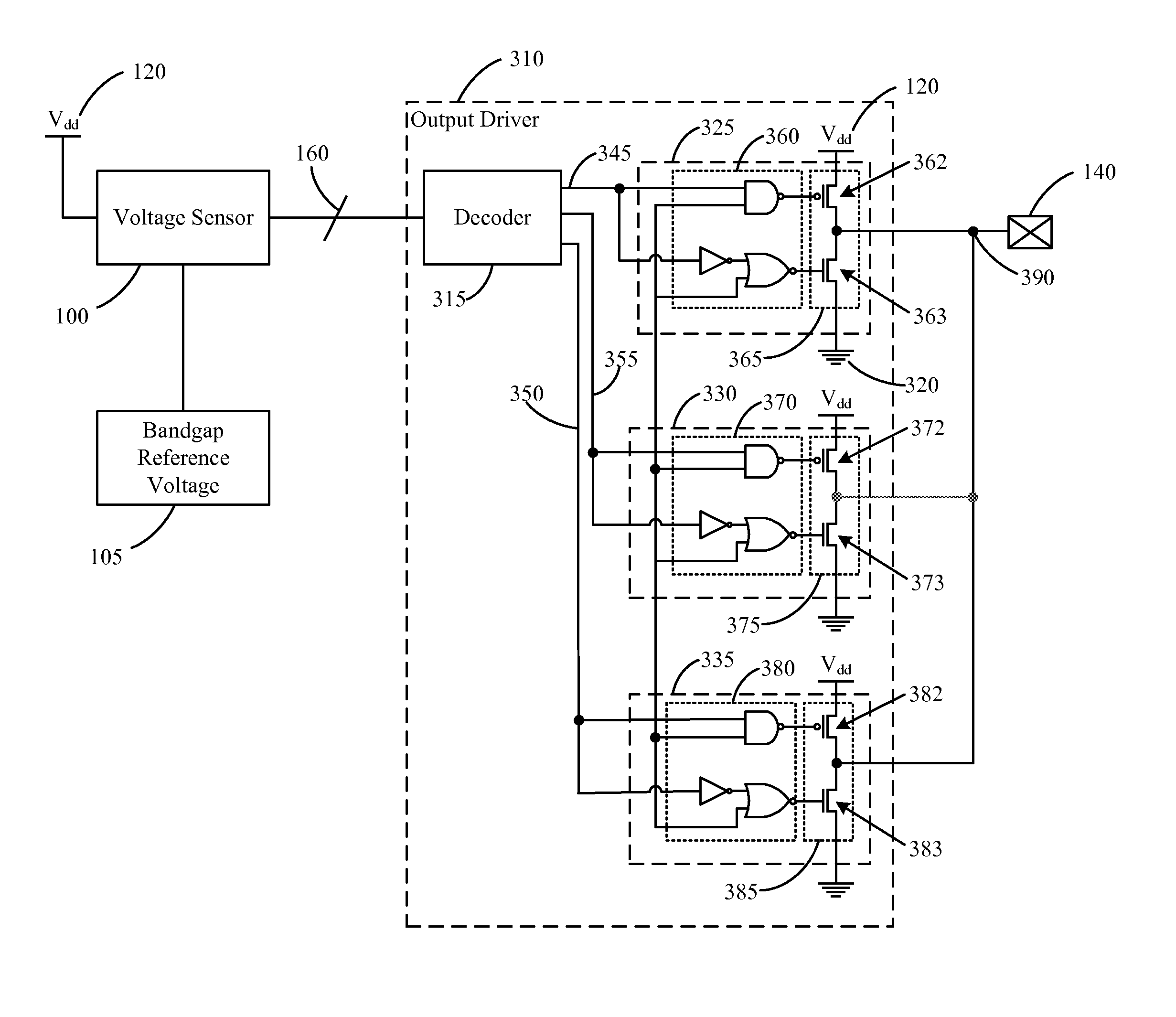
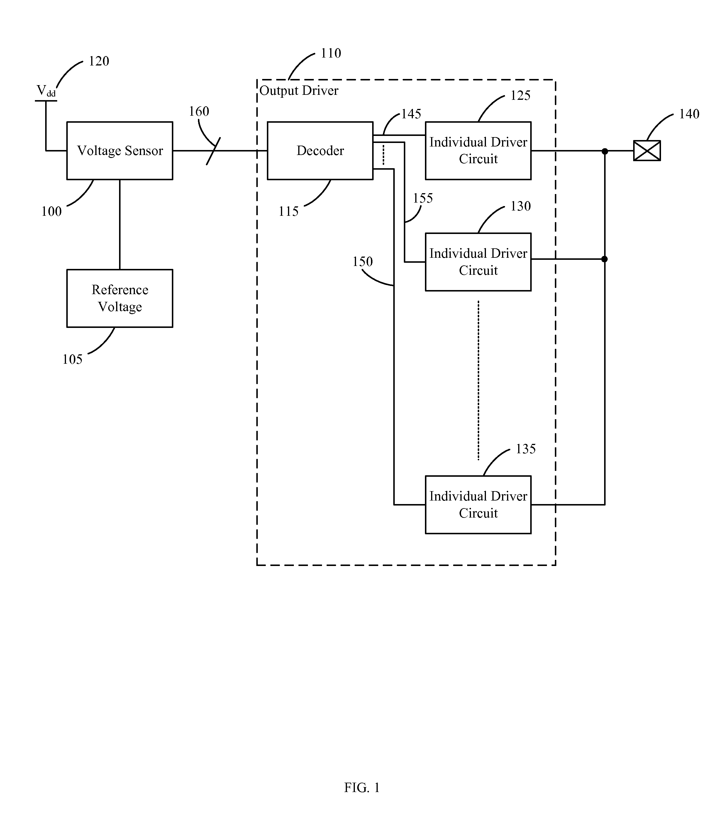
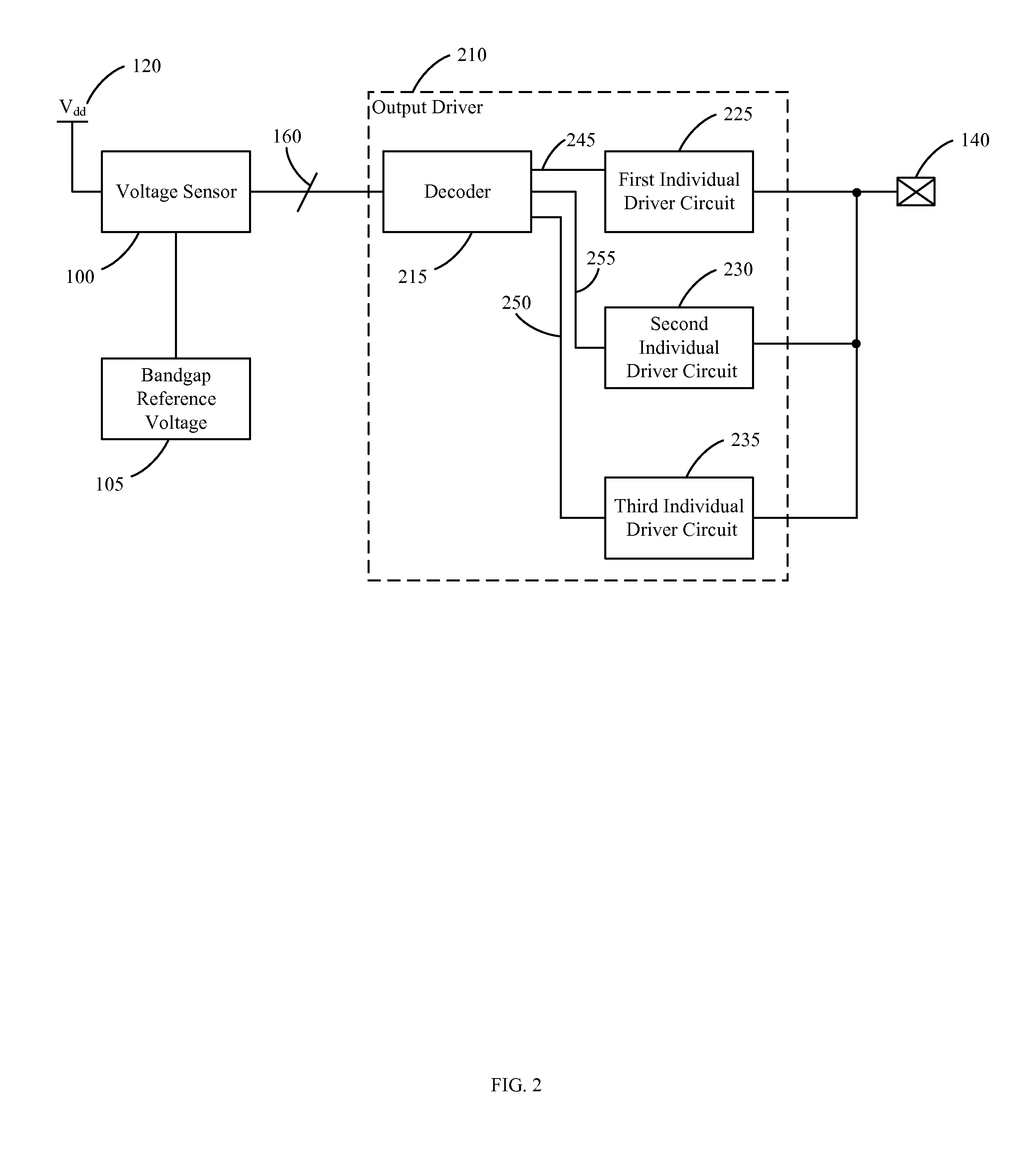
[0018]In operation of an integrated circuit is provided, an improved output driver that adapts to the voltage level of the power supply, thereby providing the same output impedance from the output driver over a range of different operating voltages.

[0019]With reference to FIG. 1, the output driver 110 includes a decoder 115 and a plurality of individual driver circuits 125, 130, 135. In one embodiment the individual driver circuits 125, 130, 135 are LVCMOS driver circuits comprising LVCMOS elements. An input of each of the individual driver circuits 125, 130, 135 is coupled to an individual output 145, 150, 155 of the decoder 115 and an output of each of the individual driver circuits 125, 130, 135 is coupled to a semiconductor pad 140 that may be coupled to a data bus or transmission line external to the output driver 110. In operation, the output driver 110 is coupled to the data bus through the semiconductor pad 140 and the output driver 110 drives a voltage on the transmission l...


PUM


Abstract

An output driver is provided that adapts an output impedance of the output driver to the voltage level of a power supply, thereby providing a constant output impedance over a range of different operating voltages. The output driver includes a plurality of individual driver circuits, each one of the plurality of individual driver circuits configured to provide a plurality of predetermined output impedances in response to a plurality of power supply voltage level inputs and a decoder. The decoder of the output driver is configured for receiving a digital codeword representative of a voltage level of a power supply coupled to the output driver and for decoding the digital codeword to activate one or more of the individual driver circuits to provide a constant output impedance from the output driver in response to the voltage level of the power supply coupled to the output driver, wherein the constant output impedance is a combination of the predetermined output impedances of the activated individual driver circuits.

Description

FIELD OF THE INVENTION[0001]This invention relates to integrated circuits comprising an output driver having an adaptable output impedance that is dependent upon the voltage level input of a supply voltage.BACKGROUND OF THE INVENTION[0002]An output driver is a common element of a semiconductor device that is typically used for storing a binary value and for communicating the binary value to other circuitry throughout the semiconductor device over a data bus. At the output driver, a voltage level represents the binary value and it is common to connect an output driver to a transmission line of the semiconductor device for communicating the binary value to a receiving circuit by driving the transmission line to a desired voltage level, representative of the binary value. When driving the transmission line, the output driver exhibits an inherent output impedance. The transmission line also has an inherent characteristic impedance. When the output impedance of the output driver is not m...

Claims


Application Information

Patent Timeline
Patent Type & Authority Patents(United States)
IPC IPC(8): H03K3/01H03K3/012
CPCH03K3/01H03K3/012H03K19/0005H03K19/00384H03K19/018571H04L25/0278
Inventor HSU, JOHN
Owner INTEGRATED DEVICE TECH INC
Learn More