Non-contact power transmission device

a power transmission device and non-contact technology, applied in the direction of rail devices, battery/fuel cell control arrangements, transportation and packaging, etc., can solve the problems of complex variable control of the matching unit, inability to achieve impedance matching, and complicated matching units, etc., to improve the transmission efficiency

Active Publication Date: 2017-04-25
TOYOTA IND CORP
View PDF15 Cites 0 Cited by
  • Summary
  • Abstract
  • Description
  • Claims
  • Application Information

AI Technical Summary

Benefits of technology

[0007]It is an object of the present invention to provide a non-contact power transmission device that can properly perform power transmission when the impedance of a load changes.
[0009]In this configuration, the impedance is adjusted by adjusting the duty ratio. Thus, when the impedance of the load changes, the duty ratio is adjusted in accordance with the change. As a result, an impedance from the output terminal of the matching unit to the load may be constant regardless of the change in the impedance of the load. In this case, there is no need to change the inductance and the capacitance of the matching unit in accordance with the change in the impedance of the load. Thus, the configuration of the matching unit may be simplified. Particularly, by adjusting the duty ratio of the adjustment unit following changes in the impedance of the load, the control of the matching unit may be simplified as compared to a configuration that performs variable control on the matching unit following changes in the impedance of the load.

Problems solved by technology

However, when the matching unit is configured to have a fixed constant, if the impedance of a load changes as the amount of power supplied to the load changes, impedance matching cannot be accomplished.
However, this would result in the matching unit being complicated and the variable control of the matching unit being complicated.
The above issue is not limited to a configuration in which non-contact power transmission is performed through magnetic field resonance and also arises when non-contact power transmission is performed through electromagnetic induction.

Method used


Image

  • Non-contact power transmission device
  • Non-contact power transmission device

Examples


Embodiment Construction

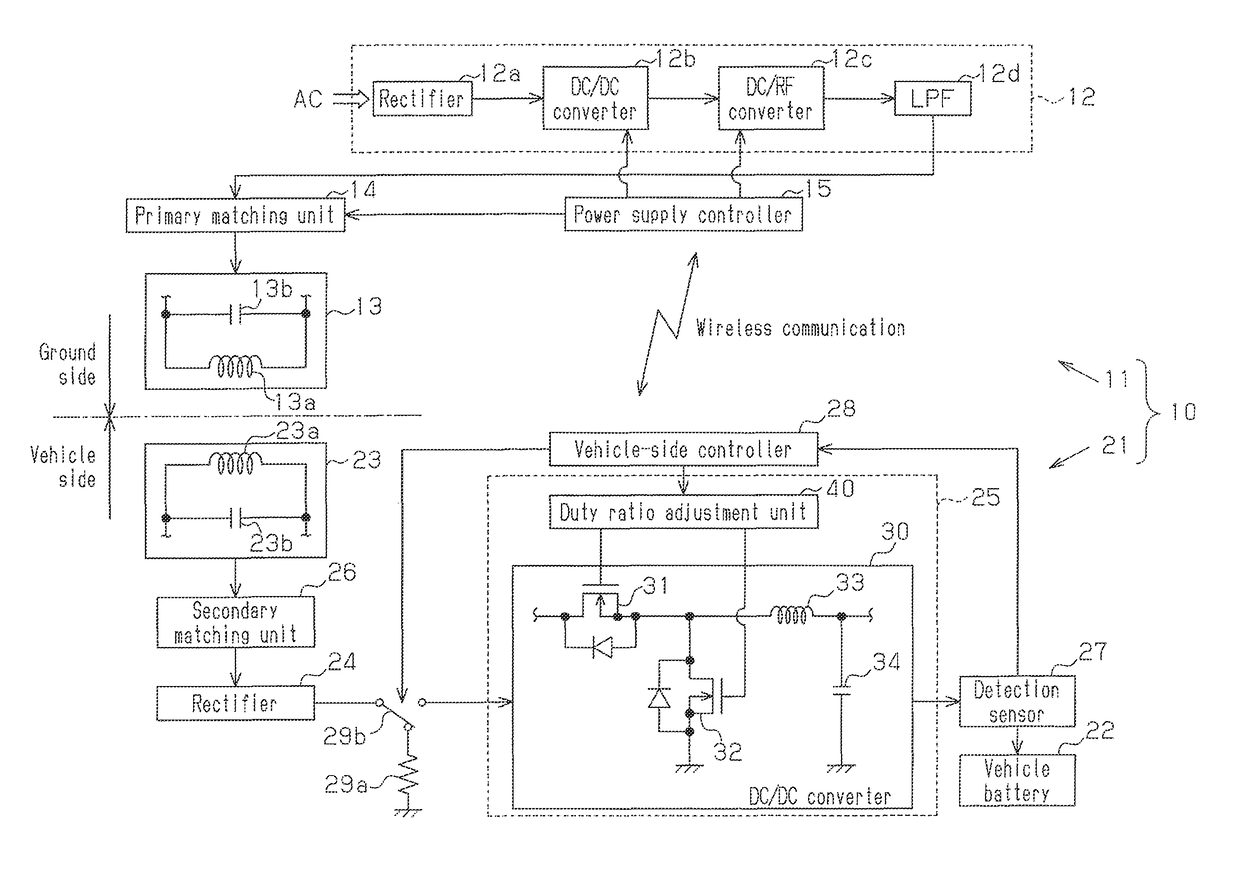
[0020]A non-contact power transmission device (non-contact power transmission system) according to the present invention will now be described.

[0021]As shown in FIG. 1, a non-contact power transmission device 10 includes a ground-side device 11 that is located on the ground and a vehicle-side device 21 that is installed in a vehicle. The ground-side device 11 corresponds to a primary device (power transmitting device), and the vehicle-side device 21 corresponds to a secondary device (power receiving device).

[0022]The ground-side device 11 includes a high frequency power supply 12 (alternating current power supply) that is capable of outputting high frequency power (alternating current power) in a predetermined frequency. The high frequency power supply 12 is configured to be capable of outputting high frequency power having a sine-wave using system power. More specifically, the high frequency power supply 12 includes a rectifier 12a, which rectifies the system power to direct curren...


PUM

PropertyMeasurementUnit
alternating current poweraaaaaaaaaa
inductanceaaaaaaaaaa
capacitanceaaaaaaaaaa

Abstract

A non-contact power transmission device equipped with a ground-side device and a vehicle-side device. The ground-side device has a primary-side coil to which alternating-current power is input. The vehicle-side device includes a secondary-side coil, a battery, a secondary-side matching device, and a charging device. The secondary-side coil receives alternating-current power from the primary-side coil in a non-contact manner. The secondary-side matching device is provided between the secondary-side coil and the battery, and has a predetermined fixed inductance and fixed capacitance. The charging device has a switching element that performs a switching operation with a prescribed cycle. The charging device adjusts the duty ratio of the switching operation in accordance with the impedance of a load.

Description

CROSS-REFERENCE TO RELATED APPLICATIONS[0001]This application is the National Stage of International Application No. PCT / JP2013 / 067222, filed Jun. 24, 2013, which claims the benefit of Japanese Application No. 2012-142202, filed Jun. 25, 2012, the disclosures of which are incorporated herein by reference in their entireties.TECHNICAL FIELD[0002]The present invention relates to a non-contact power transmission device.BACKGROUND ART[0003]In the prior art, for example, a device using magnetic field resonance is known as a non-contact power transmission device that does not use a power cord or a power transmission cable. For example, a non-contact power transmission device of patent document 1 includes a power supply device that includes an alternating current power supply and a primary resonance coil, which receives alternating current power from the alternating current power supply. Also, a vehicle, which is a power receiving device, includes a secondary resonance coil capable of perf...

Claims


Application Information

Patent Timeline
Patent Type & Authority Patents(United States)
IPC IPC(8): H02J7/00H03H7/38H02J7/02H02J5/00H01F38/14B60L11/18B60L5/00B60M7/00
CPCH03H7/38B60L11/182B60L11/1824B60L11/1861H01F38/14H02J5/005H02J7/025B60L2210/10B60L2210/30B60L2210/40B60L2240/70B60L2270/147Y02T10/705Y02T10/7005Y02T10/7044Y02T10/7072Y02T10/7216Y02T10/7241Y02T10/7291Y02T90/12Y02T90/121Y02T90/122Y02T90/127Y02T90/14Y02T90/16H02J50/10B60L58/12B60L53/126H02J2310/46H02J7/00712Y02T10/70Y02T10/72H02J50/12H02J50/80H02J50/90
Inventor KOIKE, TSUYOSHIKONDO, TADASHIKATSUNAGA, HIROSHITAGUCHI, YUICHITOGANO, HIROKIMATSUKURA, KEISUKEINOUE, KEISUKETSUNEKAWA, YUKIONO, TAKUMA
Owner TOYOTA IND CORP
Why Eureka
Try Eureka