Sensor for capturing a moving material web

a technology of moving material and sensor, which is applied in the field of sensor for capturing moving material web, can solve the problems of affecting the reliable capture of the inability of the detection light to determine the position of the moving material web from the detection light, and the inability of the detection light to accurately capture the position of the metal strip. to achieve the effect of scanning difficult material webs

Active Publication Date: 2016-08-16
TEXMAG GMBH VERTRIEBS
View PDF5 Cites 0 Cited by
  • Summary
  • Abstract
  • Description
  • Claims
  • Application Information

AI Technical Summary

Benefits of technology

[0010]In unfavourable cases it is possible, however, that the dependence of the detection light on the position of the moving material web is too small for the position of the material web to be ascertained from the detection light. For example, if the intention is to capture the position of a metal strip provided on the material web, wherein the entire material web is sprayed with clear varnish, only a relatively small contrast between the metal strip and the remaining material web is produced, which hinders reliable capturing of the position of the metal strip. In order to make possible reliable capturing of the position of the material web even under these more difficult conditions, the light sources are able to emit emission light having different polarization. Preferably, the emission light of the at least one of the light sources is polarized parallel to the plane of the material web, while the emission light of the at least one other light source is polarized perpendicular to the plane of the material web. These alignments are however not necessary. What is crucial is merely that the polarization properties as such are different. As a result, the polarization of the emission light overall can be varied by driving the light sources. Starting from the above-mentioned example, the light sources can be driven for example such that the emission light is polarized only perpendicularly. By driving the light sources with parallel polarization, the emission light by contrast is polarized parallel. By simultaneous driving of differently polarized light sources it is also possible to mix these polarization directions. It is here in principle not important whether the light sources themselves already transmit polarized light or if their unpolarized light is polarized by optical means. By appropriately choosing the polarization state using the control of the light sources, it is possible even under unfavourable conditions to reliably scan a marking on the moving material web. Provision is made in particular for the emission power of the light sources to vary such that a selected guidance criterion of the moving material web produces optimum contrast.
[0013]If the emission light or the transmission light strikes the material web at an acute angle with respect to a normal on the material web, the result is a strong dependence of the light reflection on the polarization direction in particular in the case of dielectric material webs or material webs with dielectric covering layers, such as for example clear varnish layers. It is thus possible to effectively scan difficult material webs by appropriately choosing the polarization direction or a corresponding mixing of different polarization directions.

Problems solved by technology

In unfavourable cases it is possible, however, that the dependence of the detection light on the position of the moving material web is too small for the position of the material web to be ascertained from the detection light.
For example, if the intention is to capture the position of a metal strip provided on the material web, wherein the entire material web is sprayed with clear varnish, only a relatively small contrast between the metal strip and the remaining material web is produced, which hinders reliable capturing of the position of the metal strip.
The least practical light sources provide polarized emission light.

Method used


Image

  • Sensor for capturing a moving material web
  • Sensor for capturing a moving material web

Examples


Embodiment Construction

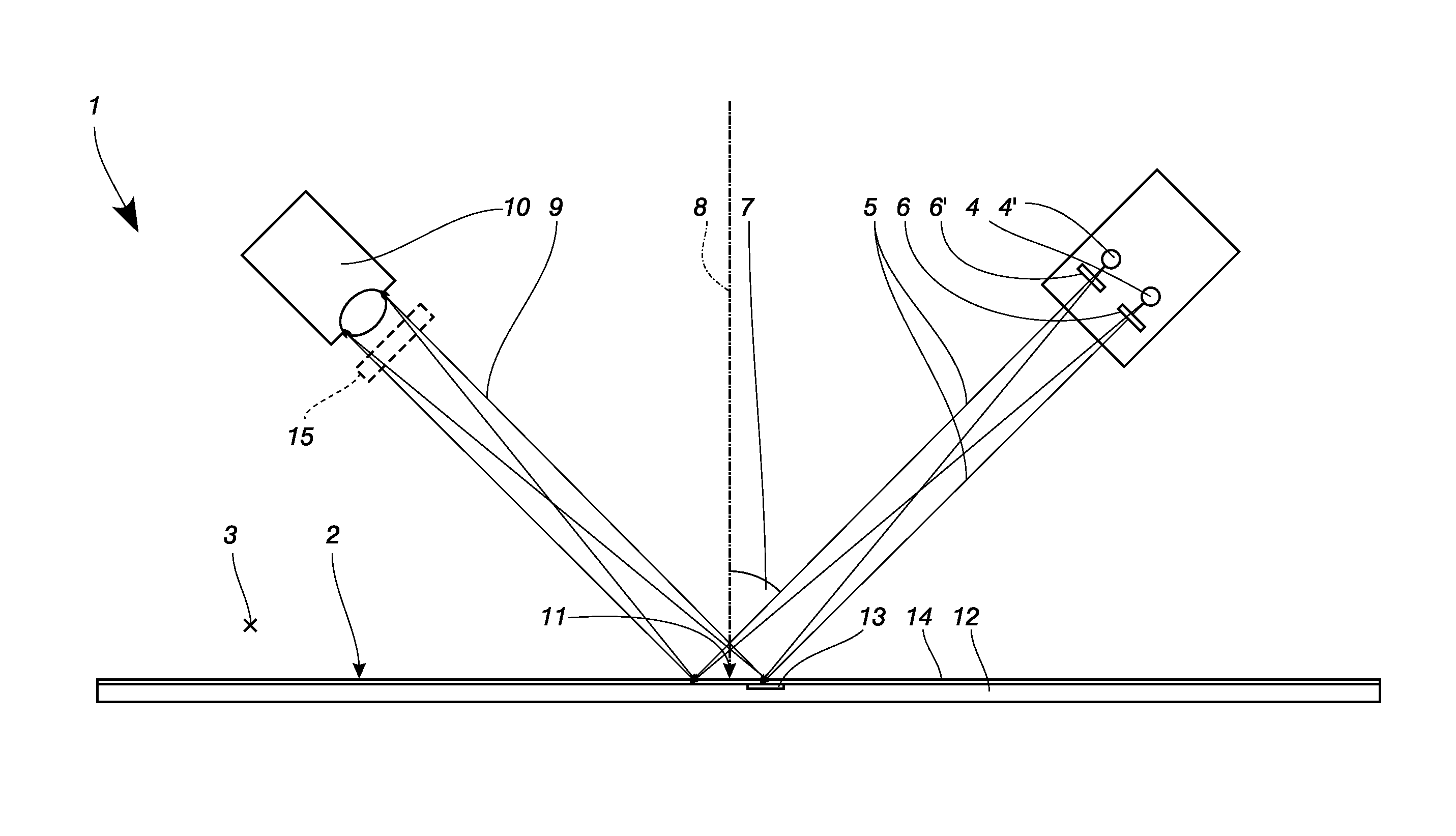
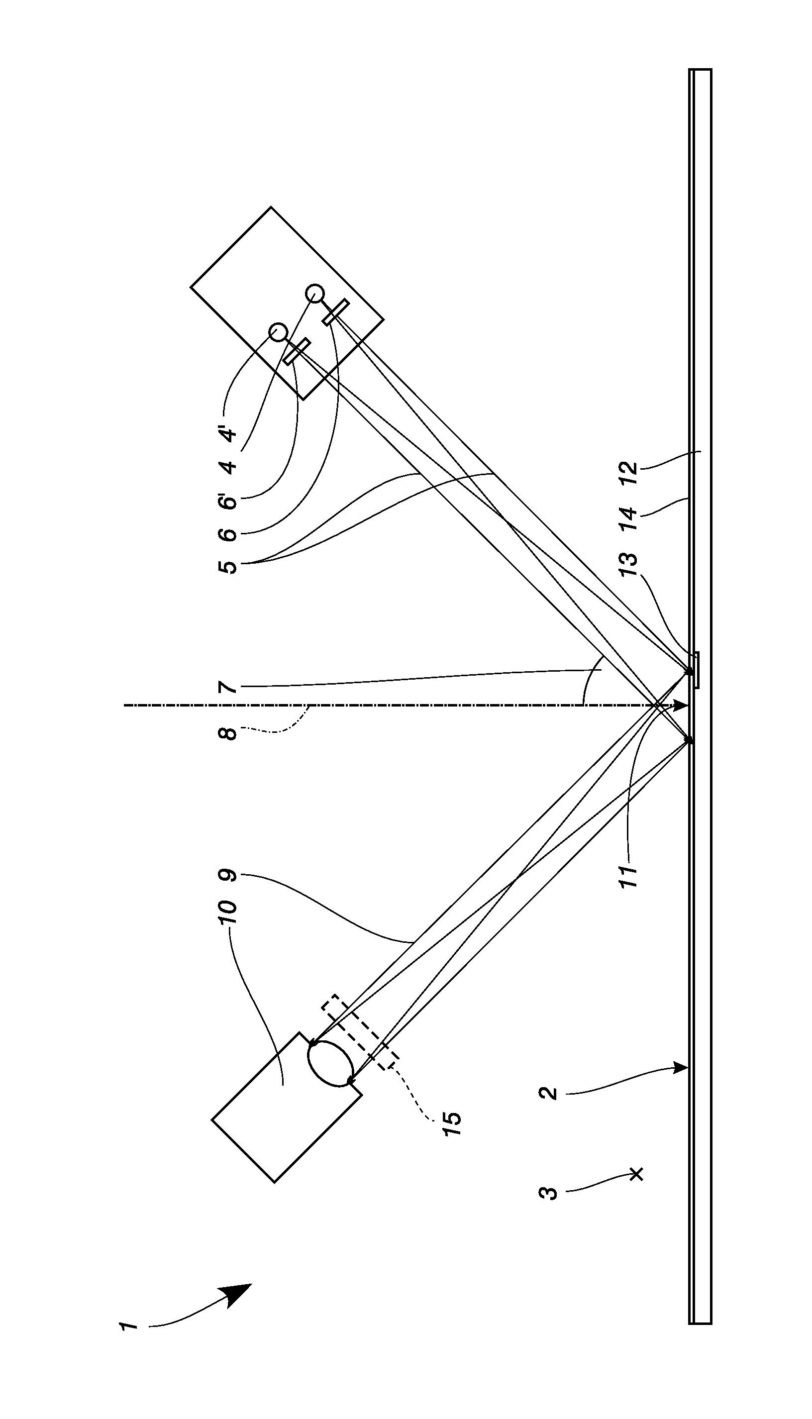
[0016]The single FIGURE shows a schematic principle illustration of a sensor 1. A sensor 1 according to FIG. 1 serves for capturing a moving material web 2, which moves along a direction of motion 3 which is directed towards the observer. The sensor 1 has two light sources 4, 4′ which emit emission light 5. Arranged downstream of the light sources 4, 4′ is a respective polarization filter 6, 6′, which generate linearly polarized emission light 5. The emission light 5 that is thus polarized strikes the material web 2 at an acute angle 7 measured with respect to a normal 8. Part of the incident light is reflected by the material web 2, wherein the reflectivity depends both on the polarization state of the incident light and on the material properties of the material web 2. The reflected detection light 9 finally travels to a light detector 10, which is configured for example as a camera. An additional polarization filter 15 can optionally be arranged upstream of the light detector 10....


PUM


Abstract

A sensor (1) serves for capturing the moving material web (2). It has light sources (4, 4′) and at least one light detector (10). The light sources (4, 4′) generate emission light (5) having different polarization. The polarization state of the emitted light can be influenced by selecting or mixing the emission light (5) of the light sources (4, 4′). Markings such as for example metal strips (13) in the material web (2) can thus be captured with the light detector (10) without problem.

Description

[0001]The present application claims priority to European Patent Application no: EP 12 006 112.2, filed Aug. 28, 2012.FIELD OF THE INVENTION[0002]The invention relates to a sensor for capturing a moving material web, in particular for capturing the position of a moving material web.DESCRIPTION OF THE PRIOR ART[0003]US 2007 / 0153285 A1 discloses an ellipsometer for determining the optical reflection properties of samples. This ellipsometer can be operated with different laser light sources in order to permit wavelength-dependent analysis. The light incidence in this case is grazing, such that the incident light encloses an angle of nearly 90° with respect to the normal on the sample surface. The reflected light is focused onto a detector using a lens arrangement, which detector detects the integral luminous flux. The sample to be analysed is here assumed to be homogeneous over the analysed surface such that no markings or peripheral edges are detectable.[0004]U.S. Pat. No. 4,210,401 d...

Claims


Application Information

Patent Timeline
Patent Type & Authority Patents(United States)
IPC IPC(8): H04N5/235G01B11/00
CPCG01B11/00H04N5/235G01N21/86H04N23/70
Inventor EISEN, JUERGENZWERGER, LARS
Owner TEXMAG GMBH VERTRIEBS
Why Eureka
Try Eureka