
Sensor for capturing a moving material web

Active Publication Date: 2014-03-06
TEXMAG GMBH VERTRIEBS
View PDF42 Cites 1 Cited by
  • Summary
  • Abstract
  • Description
  • Claims
  • Application Information

AI Technical Summary

Benefits of technology

The patent describes a method for detecting the position of a moving material web by using a polarization element between a light source and a light detector. This element can influence the polarization of the light in a way that makes it easier to capture the position of the material web, even when there is no clear contrast between the material and the surrounding environment. The method also takes into account the fact that the light reflection from the material web can be dependent on the polarization direction, so different polarization directions can be used to effectively scan difficult material webs.

Problems solved by technology

In unfavourable cases it is possible, however, that the dependence of the detection light on the position of the moving material web is too small for the position of the material web to be ascertained from the detection light.
For example, if the intention is to capture the position of a metal strip provided on the material web, wherein the entire material web is sprayed with clear varnish, only a relatively small contrast between the metal strip and the remaining material web is produced, which hinders reliable capturing of the position of the metal strip.

Method used


Image

  • Sensor for capturing a moving material web
  • Sensor for capturing a moving material web

Examples


Embodiment Construction

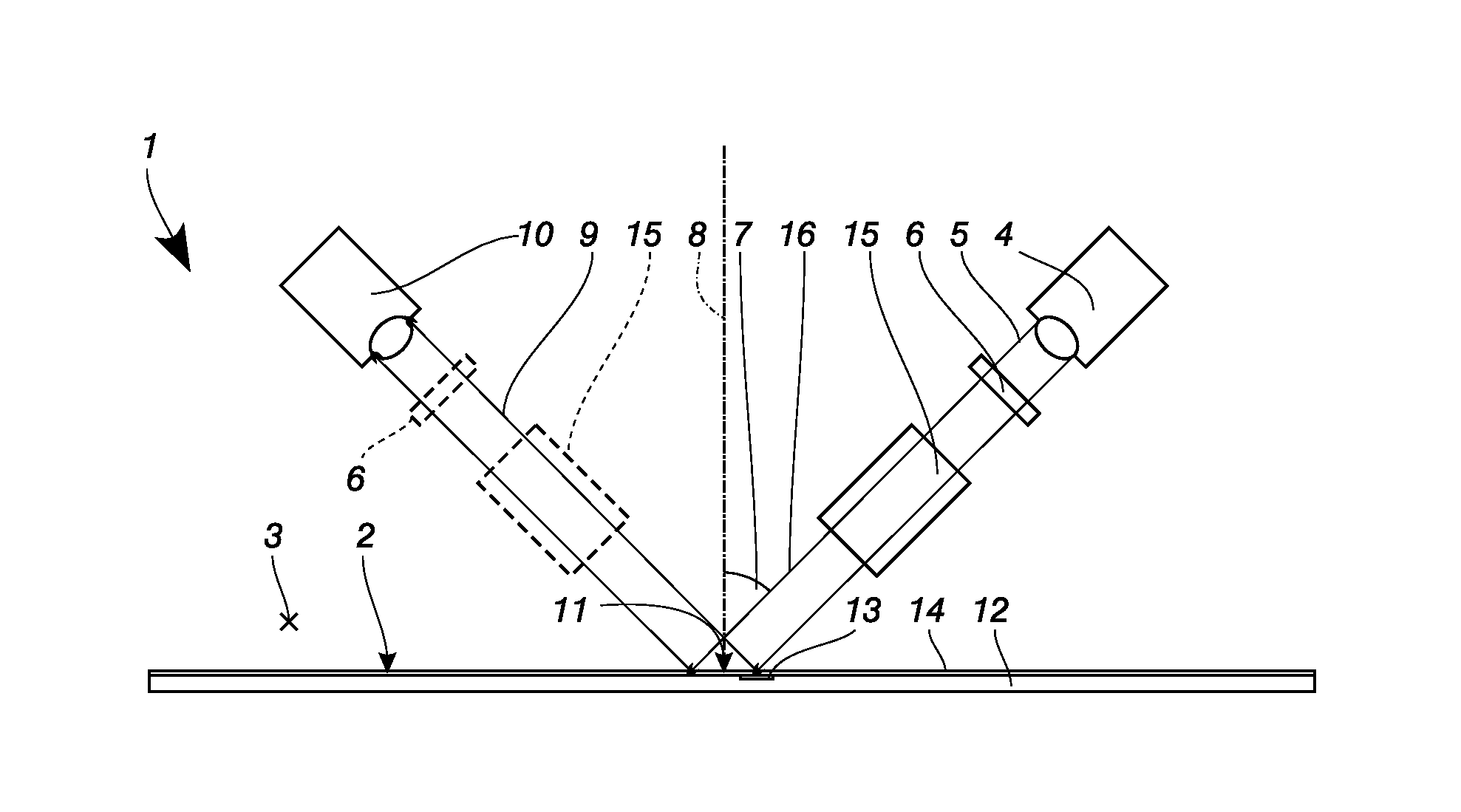
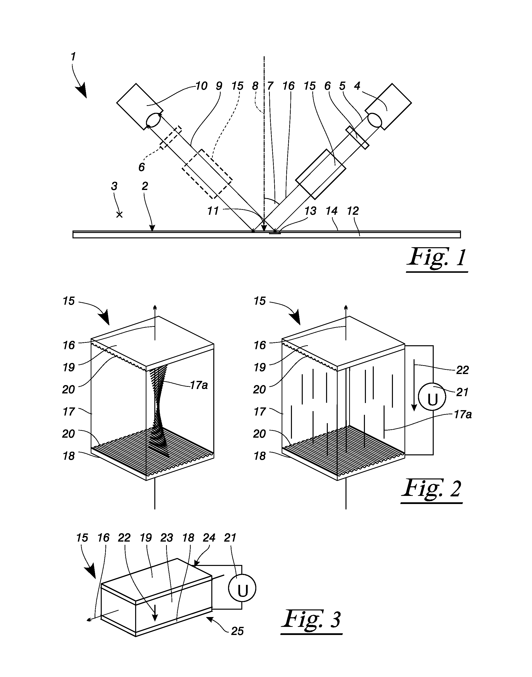
[0023]A sensor 1 according to FIG. 1 serves for capturing a moving material web 2, which moves along a direction of motion 3 which is directed towards the observer. The sensor 1 has a light source 4 which emits emission light 5. Arranged downstream of the light source 4 is a polarization filter 6, which linearly polarizes the emission light 5. The emission light 5 that is thus polarized strikes the material web 2—at an acute angle 7 measured with respect to—a normal 8. Part of the incident light is reflected by the material web 2, wherein the reflectivity depends both on the polarization state of the incident light and on the material properties of the material web 2. The reflected detection light 9 finally travels to a light detector 10, which is configured for example as a camera. This can be used to capture a detail 11 of the material web in a spatially resolved manner. An additional polarization filter 6 can optionally be arranged upstream of the light detector 10.

[0024]In the e...


PUM


Abstract

A sensor (1) serves for capturing a moving material web (2). It has at least one light source (4) and at least one light detector (10). At least one polarization element (15) is provided between the two, which polarization element influences polarization properties of the light transmitted by the polarization element (15) as a function of an electric field. Markings such as for example metal strips (13) in the material web (2) can thus be captured in the light detector (10) without problem.

Description

[0001]The present application claims priority to European Patent Application no: EP 12 006 111.4, filed Aug. 28, 2012.FIELD OF THE INVENTION[0002]The invention relates to a sensor for capturing a moving material web, in particular for capturing the position of a moving material web.DESCRIPTION OF THE PRIOR ART[0003]EP 2 157 401 A1 discloses an apparatus for measuring distances. Said apparatus consists of a light source and a light detector, which are decoupled via a beam splitter. Here, the light source transmits light through the beam splitter onto a sample to be investigated. Light reflected thereby is reflected by the beam splitter and guided to a detector. The distance of the sample from said apparatus is ascertained by capturing the time delay of the signals arriving at the detector.[0004]DE 42 44 332 C1 discloses a method for measuring the roughness of technical surfaces. Here, an electro-optically active liquid is applied onto a metallic surface of a sample to be investigated...

Claims


Application Information

Patent Timeline
IPC IPC(8): H04N5/235
CPCH04N5/235G01B11/00G01N21/86H04N23/70
Inventor EISEN, JUERGENZWERGER, LARS
Owner TEXMAG GMBH VERTRIEBS
Learn More