Heating and air-conditioning system for a motor vehicle

a technology for air-conditioning systems and motor vehicles, which is applied in the direction of position/direction control, hand-manipulated computer devices, analog and hybrid computing, etc. it can solve the problems of high fuel consumption, excessive complexity, and wear and tear of the engine when the vehicle is driven, so as to reduce the load of the front system and achieve flexibility. , the effect of reducing the load

Active Publication Date: 2016-08-23
WEBASTO AG
View PDF86 Cites 5 Cited by
  • Summary
  • Abstract
  • Description
  • Claims
  • Application Information

AI Technical Summary

Benefits of technology

[0006]For this purpose, state of the art concepts propose to combine the front system with the rear system, and, in particular, to drive a common compressor of the air-conditioning system also when the vehicle is in the stop-state, in order to cool the rear region of the vehicle. Disadvantages of this concept are high fuel consumption, wear and tear of the engine when the vehicle is in the stop-state, and additional emissions such as pollutants and noise due to the operation of the engine.
[0007]These disadvantages had been confronted in part by allowing the operation of the front system and the rear system exclusively during the running-state of the vehicle and by providing an additional self-sufficient stop-state air-conditioning system. The stop-state system operates with, for example, an electrically or mechanically driveable compressor which is supplied with power by an auxiliary motor or an auxiliary battery. Even if this concept lowers fuel consumption, it causes decreased engine wear and results in fewer emissions, it has the drawback that due to the self-sufficient stop-state air-conditioning system extensive complexity is required.
[0016]However, it is also possible that an evaporator of the front system and an evaporator of the rear system communicate with the same condenser and that the stop-state system comprises its own condenser and its own compressor. By doing so, the adaptive complexity compared to the implementation format having only a single compressor and only a single condenser is increased, but there is, however, a benefit in flexibility when integrating the stop-state air-conditioning system. By equipping the stop-state air-conditioning system with a separate condenser and a separate compressor, it is possible to fill the stop-state air-conditioning system separately with cooling agent and add it to the entire system.
[0017]Further, it can be set up such that an evaporator of the rear system and a cold accumulator of the stop-state system communicate with the same condenser and that the front system comprises its own condenser and its own compressor. By doing so, the front system is decoupled from the combined rear stop-state air-conditioning system. The load of the front system is thereby reduced, no long cooling agent conduits are necessary between the front region and the rear region, and the rear stop-state air-conditioning system can be integrated in a flexible manner without considering the front system. The compressor of the combined rear stop-state system can be driven mechanically or electrically. In the stop-state of the motor vehicle generally no operation of the compressor is required, since the cold accumulator provides the necessary cold for the stop-state air-conditioning.
[0022]The invention is based on the conclusion that, due to integration of the stop-state system into the rear system, additional possibilities for rationalization with regard to the overall system can be accomplished. Furthermore, this integration provides the prerequisite for lowering energy consumption and emissions as well as for reducing wear and tear of the components that are involved in comparison with systems with the present state of technology.

Problems solved by technology

Disadvantages of this concept are high fuel consumption, wear and tear of the engine when the vehicle is in the stop-state, and additional emissions such as pollutants and noise due to the operation of the engine.
These disadvantages had been confronted in part by allowing the operation of the front system and the rear system exclusively during the running-state of the vehicle and by providing an additional self-sufficient stop-state air-conditioning system.
Even if this concept lowers fuel consumption, it causes decreased engine wear and results in fewer emissions, it has the drawback that due to the self-sufficient stop-state air-conditioning system extensive complexity is required.

Method used


Image

  • Heating and air-conditioning system for a motor vehicle
  • Heating and air-conditioning system for a motor vehicle
  • Heating and air-conditioning system for a motor vehicle

Examples


Embodiment Construction

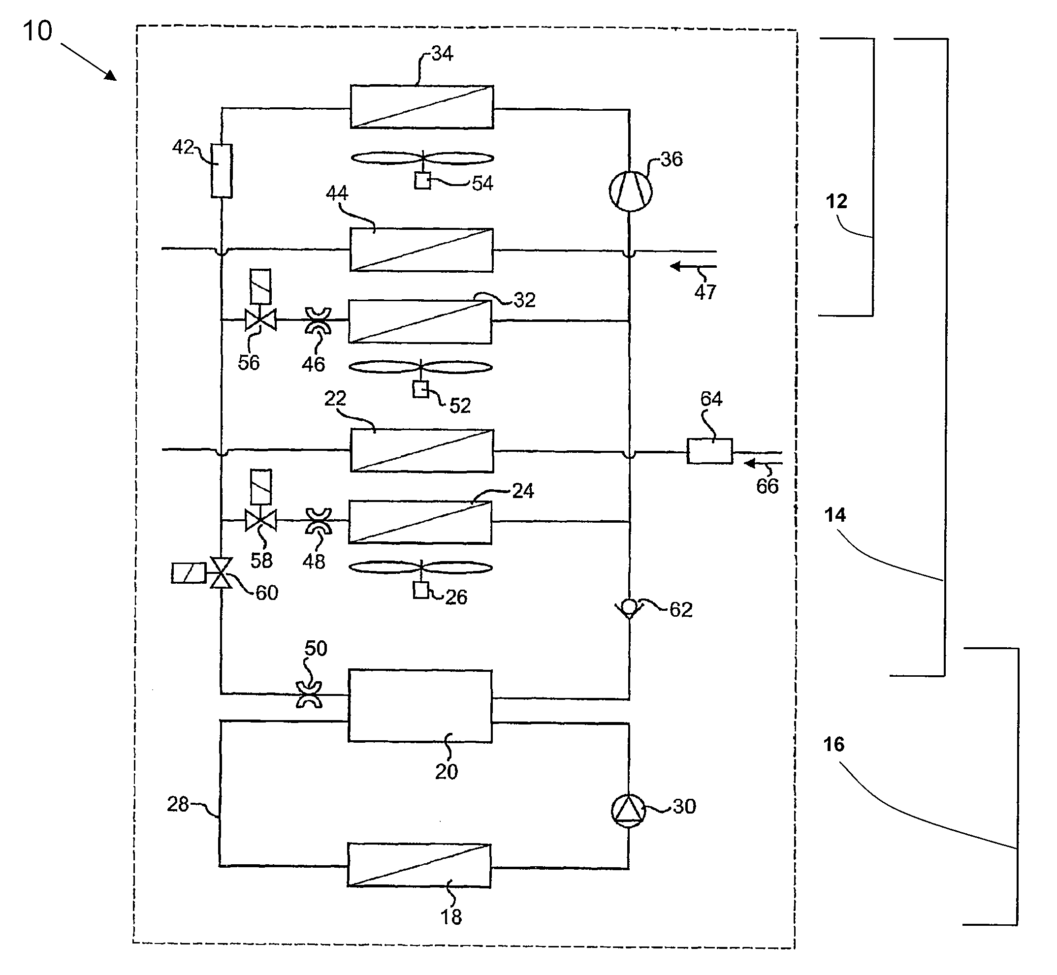
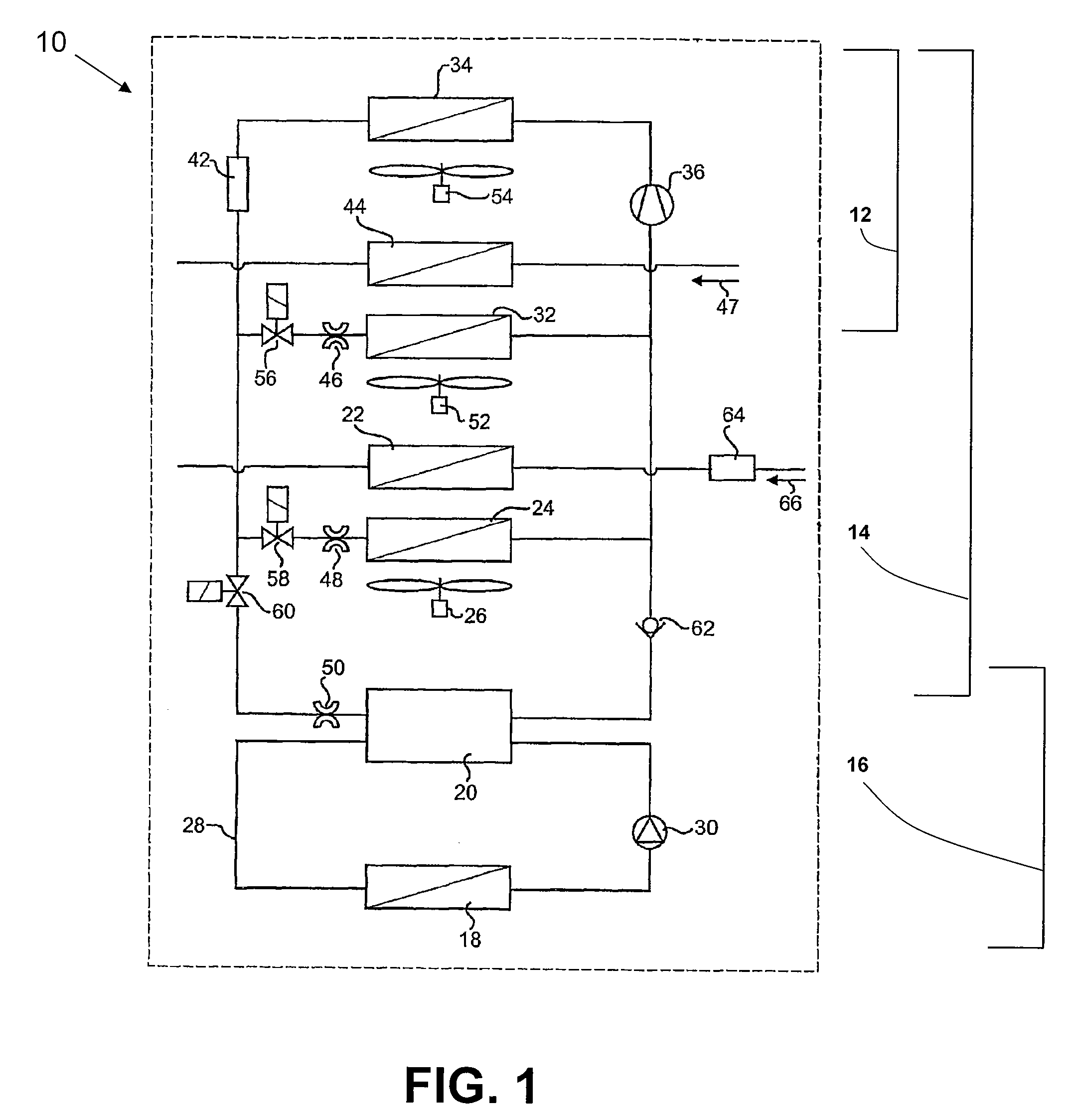
[0036]In the following detailed description of the preferred implementation format of the present invention, identical reference numerals (modulo 100) identify identical or similar components. It will be understood that those components in FIGS. 3-12 that are similar to components described in FIG. 1 are numbered the same except for the Figure number placed in front of the reference number. Thus, for example, common condenser 334 in FIGS. 3 and 434 in FIG. 4 both refer to a condenser similar and analogous to common condenser 34 in FIG. 1.

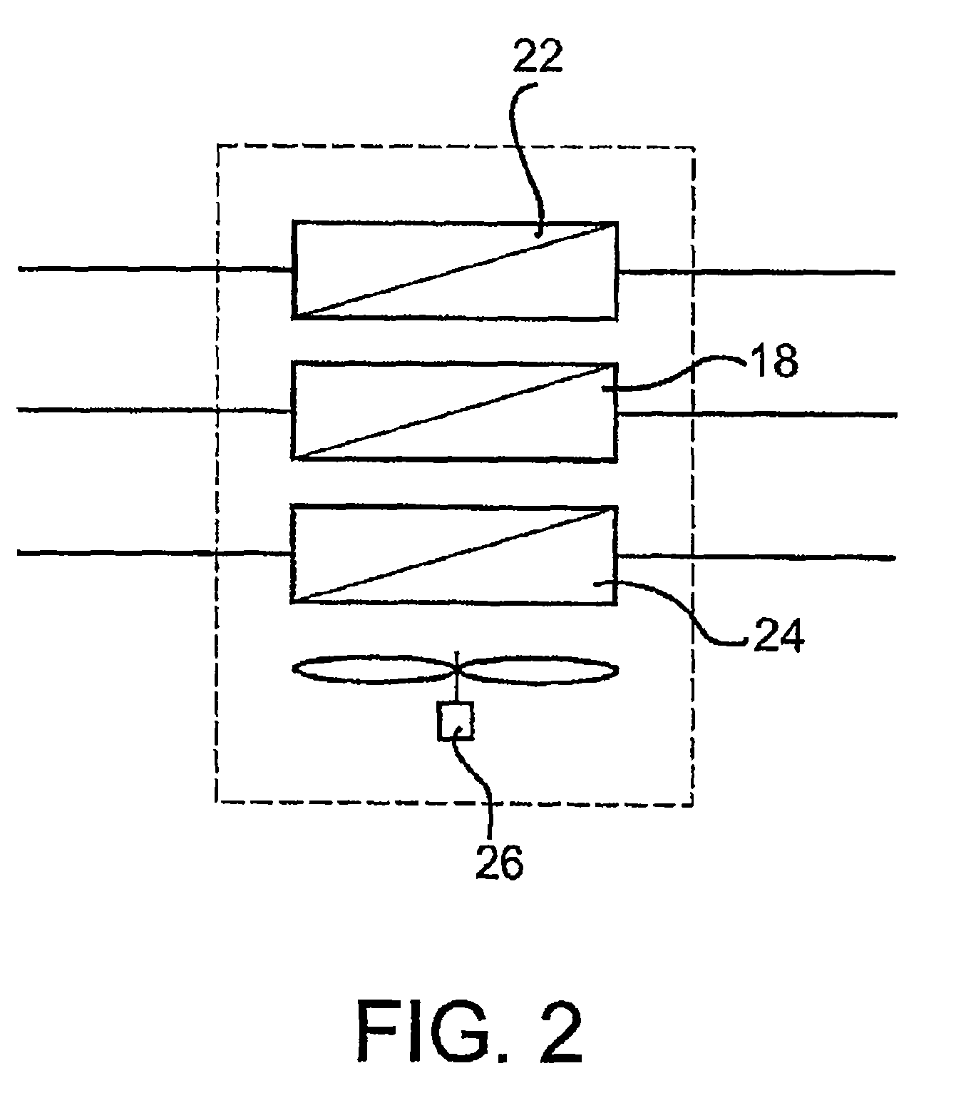
[0037]FIG. 1 shows a schematic diagram of a first implementation format of a heating and air-conditioning system according to the present invention. FIG. 2 shows two explanatory illustrations of possible geometric arrangements of components of the heating and air-conditioning system according to the present invention. The heating and air-conditioning system 10 comprises a front system 12, a rear system 14 and a stop-state system 16, wherein the ment...


PUM


Abstract

The invention relates to a heating and air-conditioning system (10) for a motor vehicle, in particular a utility vehicle, in order to heat or cool the inside of a motor vehicle during a journey and when the motor vehicle is stationary. The inside of the motor vehicle is divided into a front region and a back region, which can be heated and cooled separately, and comprises a front system (12) which is used to heat and cool the front region during a journey of the motor vehicle, a rear system (14) which is used to heat and cool the rear region during a journey of the motor vehicle and a stationary system (16) which is used to heat and to cool at least the rear region when the motor vehicle is stationary. According to the invention, the stationary system is integrated into the rear system. The invention further relates to a method for heating and air-conditioning a motor vehicle by means of a heating and air-conditioning system (10).

Description

CROSS-REFERENCE TO RELATED APPLICATIONS[0001]This application is a 35 U.S.C. §371 National Stage entry of PCT / EP2005 / 003973, filed Apr. 15, 2005, which claims priority from German Patent Application No. 102004019 607.9, filed Apr. 22, 2004, the contents of which are herein incorporated by reference to the extent allowed by law.BACKGROUND OF THE INVENTIONField of the Invention[0002]The invention relates to a heating and air-conditioning system for a motor vehicle, in particular a utility vehicle, in order to heat and cool the inside of a motor vehicle during a running-state and a stop-state of the motor vehicle, wherein the inside of the motor vehicle is divided into a front region and a rear region, which can be heated and cooled separately. The heating and air-conditioning system comprises a front system for heating and cooling the front region during the running-state of the motor vehicle, a rear system for heating and cooling the rear region during the running-state of the motor ...

Claims


Application Information

Patent Timeline
Patent Type & Authority Patents(United States)
IPC IPC(8): B60H1/32B60H1/03B60H1/00
CPCB60H1/00064B60H1/005B60H1/03B60H1/00207B60H1/00885B60H2001/002B60H2001/00928B60H2001/00949
Inventor KHELIFA, NOUREDDINEKRAEMER, WOLFGANG
Owner WEBASTO AG
Why Eureka
Try Eureka